


Application Note
31 of 53
V 1.0
2019-04-01
IM393 Application note
IM393 IPM Technical Description
Function and protection circuit
4 ~ 11.2
As the undervoltage lockout function is activated, control input signals are
blocked, and a fault signal VFO is generated.
11.2 ~ 13.5
IGBTs will be operated in accordance with the control gate input. Driving
voltage is below the recommended range, so V
CE(sat)
and the switching losses
will be larger than under normal conditions. High-side IGBTs cannot operate
after V
BS
initial charging, as V
BS
cannot reach V
BSUV+
.
13.5 ~ 16.5 for VDD
12.5 ~ 17.5 for VBS
Normal operation. This is the recommended operating condition.
V
DD
of 15 V is recommended when only integrated bootstrap circuitry is used.
16.5 ~ 20 for VDD
17.5 ~ 20 for VBS
IGBTs are still in operation. Because driving voltage is above the
recommended range, IGBTs’ switching is faster. It causes increased system
noise. And peak short-circuit current might be too large for proper operation
of the short-circuit protection.
Over 20
Control circuit in the IM393-XX might be damaged.
5.4
Over-temperature protection
IM393-XX have V
TH
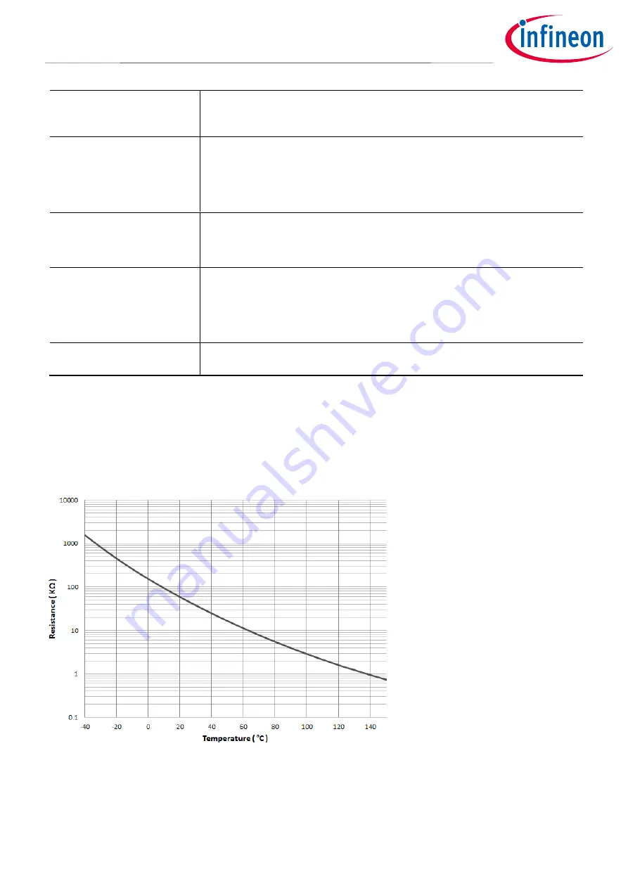
pins for temperature-sensing. Figure 23 shows internal thermistor-resistance characteristics
according to the thermistor temperature. For over-temperature protection, a circuitry is introduced in this
section. As shown in Figure 24, the V
TH
pin is connected directly to the ADC terminal of the microcontroller. This
circuit is very simple, and the six IGBTs have to be shut down by a command issued from the microcontroller.
Figure 23
Internal thermistor-resistance characteristics according to thermistor temperature
NTC resistance can be translated to a voltage that can be read by the microcontroller using external resistance
R1. For example, when R1 is 2 k
Ω
, then VFO at about 100°C of the thermistor temperature is 2.95 V
typ
at V
ctr
= 5 V
and 1.95 V at V
ctr
= 3.3 V, as shown in Figure 25.


