


Application Note
17 of 53
V 1.0
2019-04-01
IM393 Application note
IM393 IPM Technical Description
Interface circuit and layout guide
4
Interface circuit and layout guide
4.1
Input/output signal connection
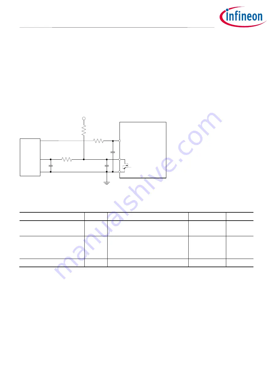
The following shows the I/O interface circuit between microcontroller and IM393-XX. Because the IPM input
logic is active-high with internal pull-down resistors, pulled-up resistors are not required. The RFE output is
open-drain MOSFET configured. Thus this signal should be pulled up to the positive side of 5 V or 3.3 V external
logic power supply with a resistor. The resistor should be carefully chosen to limit current (e.g. 1.2 MΩ). In case
of over-current, the RFE pin will get low as the MOSFET turns ON. When the over-current condition is over, the
MOSFET will then turn OFF, however, all the IGBTs will remain OFF until the fault is cleared (see section 5.3).
Micro
Controller
COM
5V-Line (or 3.3V-Line)
HIN / LIN
RFE
1k
Ω
1nF
CIPOS
TM
Tiny
1.2MΩ
1nF
100
Ω
1nF
Figure 10
Recommended microcontroller I/O interface circuit
Table 4
Maximum rating of input and RFE pin
Item
Symbol
Condition
Rating
Unit
Module supply voltage
V
DD
Applied between
V
DD
– COM
-0.3 ~ 20
V
Input voltage
V
IN
Applied between
HIN(U), HIN(V), HIN(W) – COM
LIN(U), LIN(V), LIN(W) – COM
-0.3 ~ 20
V
Fault output supply voltage
RFE
Applied between RFE – COM
-0.3 ~ 20
V
The input and fault output maximum rating voltages are listed in Table 4. It is recommended to use 5 V logic
supply, which is the same for the input signals of the fault output. Bypass capacitors should be mounted as
close as possible to the RFE pin to avoid any noise that might switch the open-drain MOSFET ON.


