Page
17
of
31
6 PROGRAM MODE (I.E. IN-WORKOUT FUNCTIONALITY)
Upon transitioning to this mode time shall begin incrementing, distance shall begin accumulating, calories shall
begin accumulating, and all other displays shall become active. The specifics of the workout views are described
below.
6.1 STANDARD WORKOUT SCREENS
For quick workouts that are initiated by hitting the
QUICK START
button from the
IDLE SCREEN
or workouts that
are initiated by selecting a
TIME GOAL
,
DISTANCE GOAL
, or
CALORIE GOAL
the following screens shall be
provided during the workout.
The screen above is the initial screen that is displayed upon beginning a workout. The following fields are present:
Time
–
The elapsed time for the workout in MM:SS format
Pace
–
The amount of time, in MM:SS format, it will take to row/ski 500 meters based on the current stroke
rate
Stroke Rate
–
The rate, in strokes per minute, the user is rowing or skiing
Distance
–
The distance, in meters, the user has “traveled” in the given workout
Calories
–
The amount of calories the user has burned through the workout
Watts
–
The amount of work the user is currently performing in the workout
Heart Rate
–
The user’s current heart rate as measured from their wireless HR strap
Level
–
The current resistance level from 1 to 20 displayed as a horizontal bar graph that fills from left to
right; the level correlates to the position of the magnets relative to the flywheel
The calculations for all data displayed during the workout can be found in section
9 FORMULAS
for later in this
document.
Page
27
of
31
7
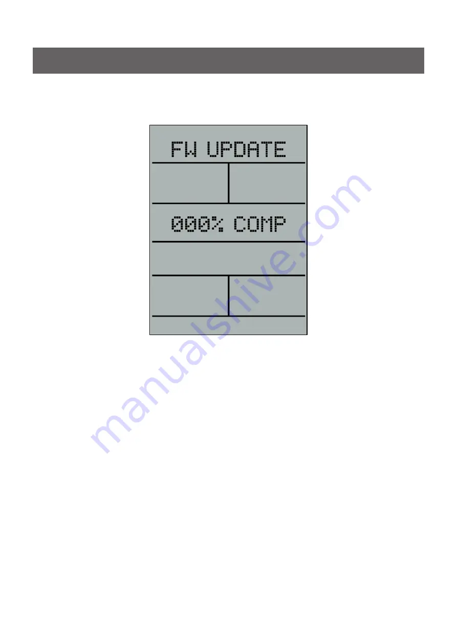
.5 UPDATE FIRMWARE SCREEN
The graphic below shows the
FW UPDATE
screen:
The console shall provide a means for updating its firmware. At a minimum, the console shall be flash-able via a
USB port on the console. The user shall be able to copy a new firmware file to a USB stick and that USB memory
stick can then
be inserted into the console’s provided USB port. Once the USB memory stick is installed in the
USB port the user shall be able to go to the
FW UPDATE
screen above. The user can then press the
ENTER
button to initiate the program upload. During the upload process the user shall be presented with a message
indicating status. The possible messages are as follows:
IDLE
–
Shown when there is no USB installed
in the console’s USB port
NO FILE
–
Shown when a USB stick is installed in the console’s USB port but there is no firmware file
found
READY
–
Shown when the USB stick is inserted and a new firmware file is present on the device
XXX% COMP
–
This message shall be shown during the upload
COMPLETE
–
This message shall be shown after a successful upload of the file
FAILED
–
This message shall be shown if an error occurs during the upload process
NOTE: Pressing the ENTER button will only have an effect when the console is in the READY state defined
above.
The
STOP
button shall behave differently depending on the state the upload process is in. Below is a list of
behaviors for the
STOP
button:
When either the
IDLE
,
READY
, or
COMPLETE
message is being displayed, if the user presses the
STOP
button then the system shall exit this state and transition to the
SETTINGS
screens
When the
XXX% COMP
message is being displayed then the
STOP
button shall be deactivated (i.e.
system shall not do anything when STOP is pressed)
When the
FAILED
message is being displayed, if the user presses the
STOP
button the system will ignore
the partially uploaded file, transition to the
SETTINGS
screen, and continue running the existing firmware
─
57
─
Console Panel Functions
Summary of Contents for HSR007
Page 13: ... 13 Parts List and Exploded View Base Frame ...
Page 14: ... 14 Parts List and Exploded View Base Frame ...
Page 15: ... 15 Parts List and Exploded View Base Frame ...
Page 16: ... 16 Parts List and Exploded View Base Frame ...
Page 17: ... 17 Parts List and Exploded View Base Frame ...
Page 28: ...Overall 28 Parts List and Exploded View ...
Page 59: ......


