21
2-2
INS
TALLER
US
ER
MAINTEN
AN
CE TECHNI
CI
AN
Insufficient circulation.
This occurs if the boiler
overheats due to insufficient water circulating in
the primary circuit (code 27); the causes can be:
- low system circulation; check that no shut-off
devices are closed on the heating circuit and
that the system is free of air (deaerated);
- circulating pump blocked; free the circulating
pump.
If this phenomenon occurs frequently, contact
a qualified technician for assistance (e.g.
Authorized After-Sales Technical Assistance
Service).
Loss of Remote Control communication.
This occurs 1 minute after communication
loss between the boiler and the remote control
(code 31). To reset the error code, switch
voltage to the boiler off and then back on
again. If this phenomenon occurs frequently,
contact a qualified technician for assistance (e.g.
Authorized After-Sales Technical Assistance
Service).
Low power supply voltage.
This occurs when
the power supply voltage is lower than the
allowed limits for the correct functioning of
the boiler. If normal conditions are restored,
the boiler re-starts without having to be reset.
If this phenomenon occurs frequently, contact
a qualified technician for assistance (e.g.
Authorized After-Sales Technical Assistance
Service).
Loss of flame signal.
This occurs when the
boiler is ignited correctly and the burner flame
switches off unexpectedly; a new attempt at
ignition is performed and if normal conditions
are restored, the boiler does not have to be
reset. If this phenomenon occurs frequently,
contact a qualified technician for assistance (e.g.
Authorized After-Sales Technical Assistance
Service).
Block due to loss of continuous flame signal.
This occurs if the "Flame signal loss" error occurs
6 times consecutively in 8.5 minutes (38)”. To
eliminate the block, the Reset button (1) must be
pressed. If this phenomenon occurs frequently,
contact a qualified technician for assistance (e.g.
Authorized After-Sales Technical Assistance
Service).
2.6 BOILER SHUTDOWN
For complete boiler switch-off, press the “off”
button, disconnect the onmipolar switch outside
of the boiler and close the gas cock upstream
from the appliance. Never leave the boiler
switched on if left unused for prolonged periods.
2.7 RESTORE HEATING SYSTEM
PRESSURE
Periodically check the system water pressure.
The boiler manometer should read a pressure
between 1 and 1.2 bar.
If the pressure is below 1 bar (with the circuit cool)
restore normal pressure via the cock located in the
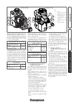
lower part of the boiler (Fig. 2-2).
N.B.:
close the cock after the operation.
If pressure values reach around 3 bar the safety
valve may be activated.
In this case contact a professional technician
for assistance.
In the event of frequent pressure drops, contact
qualified staff for assistance to eliminate the
possible system leakage.
2.8 DRAINING THE SYSTEM.
To drain the boiler, use the special draining
valve (Fig. 2-2).
Before draining, ensure that the filling valve is
closed.
2.9 ANTI-FREEZE PROTECTION.
The boiler has an anti-freeze function that
switches on automatically when the temperature
falls below 4°C (standard protection to minimum
temperature of -5°C). In order to guarantee
the integrity of the appliance and the domestic
hot water heating system in zones where the
temperature falls below zero, we recommend
the heating system is protected using anti-freeze
liquid and installation of the Immergas Anti-
freeze Kit in the boiler (Par. 1.3). In the case
of prolonged inactivity (second case), we also
recommend that:
- the electric power supply is disconnected;
- the heating circuit and boiler domestic water
circuit must be drained. In systems that are
drained frequently, filling must be carried
out with suitably treated water to eliminate
hardness that can cause lime-scale.
2.10 CASE CLEANING.
Use damp cloths and neutral detergent to clean
the boiler casing. Never use abrasive or powder
detergents.
2.11 DECOMMISSIONING.
In the event of permanent shutdown of the boiler,
contact professional staff for the procedures and
ensure that the electrical, water and gas supply
lines are shut off and disconnected.
Key:
1 - Filling valve
2 - Draining valve
Bottom view.
Summary of Contents for MINI EOLO 24 3E
Page 1: ...MINI EOLO 24 3E Instruction and warning book 1 038773ENG ...
Page 2: ......
Page 28: ...28 3 5 4 4 5 6 6 d d c INSTALLER USER MAINTENANCE TECHNICIAN ...
Page 33: ...33 ...
Page 34: ...34 ...
Page 35: ...35 ...

