17
A
B
C
D
INS
TALLER
US
ER
MAINTEN
AN
CE TECHNI
CI
AN
H
ea
d (m H
2
O)
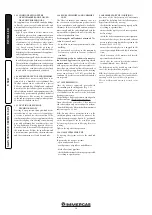
Flow rate (l/h)
H
ea
d (kP
a)
Head available to the system.
A = Head available to the system at
maximum speed with by-pass
excluded.
B = Head available to the system at
maximum speed with by-pass
inserted.
C = Head available to the system
at second speed with by-pass
excluded.
D = Head available to the system
at second speed with by-pass
inserted.
A
B
C
D
1.20 CIRCULATION PUMP.
The boilers are supplied with a built-in
circulation pump with 3-position electric speed
control. The boiler does not operate correctly
with the circulation pump on first speed. To
ensure optimal boiler operation, in the case
of new systems (single pipe and module) it is
recommended to use the pump at maximum
speed. The circulation pump is already fitted
with a capacitor.
Pump release.
If, after a prolonged period of
inactivity, the circulation pump is blocked,
unscrew the front cap and turn the motor shaft
using a screwdriver. Take great care during this
operation to avoid damage to the motor.
By-pass Regulation (part. 25 Fig. 1-30).
If
necessary, the by-pass can be regulated according
to system requirements from a minimum (by-
pass excluded) to a maximum (by-pass inserted)
represented by the graphics (Fig. 1-29). Make the
regulation using a flat head screwdriver, turn
clockwise and insert the by-pass, anti-clockwise
it is excluded.
1.21 KITS AVAILABLE ON REQUEST.
• System cut-off valves kit. The boiler is designed
for installation of system interception cocks
to be placed on flow and return pipes of the
connection assembly. This kit is particularly
useful for maintenance as it allows the boiler to
be drained separately without having to empty
the entire system.
• Polyphosphate dispenser kit. The polyphosphate
dispenser reduces the formation of lime-scale
and preserves the original heat exchange and
domestic hot water production conditions.
The boiler is prepared for application of the
polyphosphate dispenser kit.
• Covering kit. If installed outdoors in a
partially sheltered place with direct air intake,
it is compulsory to mount the appropriate top
protection cover for the correct functioning of
the boiler and to protect it from adverse weather
conditions (Fig. 1-10); or, if installed indoors in
configuration type B, it is compulsory to mount
the appropriate top protection cover along with
the flue exhaust kit.
• Anti freeze kit with resistance (on request).
If the boiler is installed in a place where the
temperature drops below -5°C and if the gas
supply fails, the appliance may freeze. To
prevent freezing of the domestic hot water
system, an anti freeze kit with an electrical
resistance can be fitted from the relative cable
and from a control thermostat.
The above-mentioned kits are supplied complete
with instructions for assembly and use.
Summary of Contents for MINI EOLO 24 3E
Page 1: ...MINI EOLO 24 3E Instruction and warning book 1 038773ENG ...
Page 2: ......
Page 28: ...28 3 5 4 4 5 6 6 d d c INSTALLER USER MAINTENANCE TECHNICIAN ...
Page 33: ...33 ...
Page 34: ...34 ...
Page 35: ...35 ...

