background image

8

SET-UP AND ASSEMBLY

Before beginning assembly, carefully read the
following information and instructions:

• Place all parts in a cleared area and remove the

packing materials from the spa shell; do not dis-
pose of the packing materials until assembly is
completed and the spa is in operation. 

• Assembly requires two people.

• Note: Some small parts may have been pre-

attached for shipping. If a part is not in the parts
bag, check to see if it has been pre-attached.   

• During assembly, make sure that all parts are ori-

ented as shown in the drawings. 

• Read each assembly step before you begin. 

• Tighten all parts as you assemble them, unless

instructed to do otherwise. 

ASSEMBLY REQUIRES THE FOLLOWING
TOOLS (not included):  

• One (1) phillips screwdriver

1. Before beginning assembly, make sure that you

have read and understand the information on
the previous two pages.

Remove the four screws from the access cover on
the console side of the spa. Remove the access
cover by sliding it down and then pulling the bottom
of it away from the spa. Be careful not to damage
the spa shell.

Remove the Power Cord with the GFCI from inside
the spa.

2. Locate and check the positions of the two cut-off

valves. The cut-off valves may have been closed at
the factory during manufacturing. However, the cut-
off valves must be open for spa operation. To open
the valves, hold the handles and turn them until you
can pull them out to the open position. IMPORTANT:
THE MOTOR WILL BE DAMAGED IF IT IS OPER-
ATED WITH THE CUT-OFF VALVES CLOSED.

Close the valve knob on the drain hose. Thread the
cap onto the drain hose. Thread the drain plug into
the Pump Motor (13). Tighten the two pump fittings.   

2

Cut-off

Valve

Pump

Fittings

Cut-off

Valve

Drain

Plug

Drain Hose

Valve

Knob

Cap

13

Screws 

Power Cord

Access

Cover 

1

All manuals and user guides at all-guides.com

Summary of Contents for 831.105021

Page 1: ...before using this equipment Save this manual for future reference USER S MANUAL www imagefitness com Visit our website at To schedule repair service or to purchase parts call SEARS toll free at 1 800...

Page 2: ...ERAPY SPA 7 SET UP AND ASSEMBLY 8 USING THE HYDROTHERAPY SPA 10 MAINTENANCE 14 TROUBLE SHOOTING 18 PART LIST 20 EXPLODED DRAWING 21 ORDERING REPLACEMENT PARTS Back Cover LIMITED WARRANTY Back Cover 2...

Page 3: ...s high as 150 F 65 C in a matter of minutes if exposed to the sun while it is empty These high temperatures can cause significant damage such as blis tering of the shell surface and warping of the spa...

Page 4: ...38 C may be injurious to your health If you plan to remain in the hydrotherapy spa for more than 10 to 15 minutes lower the temperature to 100 F 38 C or below Lower temperatures are also recommended f...

Page 5: ...mum Breaker Fuse 40 Amps 39 A green terminal or a terminalmarked G GR Ground Grounding or with the symbol is located inside the supply terminal box or compartment To reduce the risk of electric shock...

Page 6: ...the specialized treatment you need to feel your best For your safety and benefit read this manual care fully before using the RENEW 510 If you have addi tional questions please call our Customer Serv...

Page 7: ...that is built flush with the top of the spa provided you leave access to the motor for ser vice 8 Make sure to consider such factors as aesthetics or privacy that may affect the safety or enjoyment o...

Page 8: ...the information on the previous two pages Remove the four screws from the access cover on the console side of the spa Remove the access cover by sliding it down and then pulling the bottom of it away...

Page 9: ...ply a little soap or wax to the screw threads Attach the other three Buckles 2 to the wood panels in the same way 18 Spa Spa Strap 2 2 1 Strap Latch 5 Before using the spa follow the instructions on p...

Page 10: ...ESTING AND TREATING THE WATER The hydrotherapy spa comes with a starter chemical pack for maintaining the water in the spa Disregard the directions on the individual packages of QUICK pHix It DOWN and...

Page 11: ...k Note Each thera jet can be shut off by being pressed in and turned back on by being pulled out The filter C can be removed for cleaning and replacement see page 17 The suction vent D located near th...

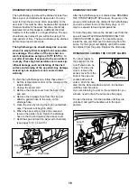
Page 12: ...ur filter cycle time Then press the jet button again If the filter cycle time is not changed it will default to 2 hours Jet Button Turns the spa jets on and off If the but ton is pressed once the spa...

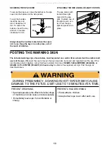
Page 13: ...G Spa heat speeds up the effect of alcohol drugs or medicine and can cause unconsciousness Immediately leave spa if uncomfortable or sleepy DURING PREGNANCY SOAKING IN HOT WATER MAY CAUSE DAMAGE TO TH...

Page 14: ...sealants work best in your climate CLEANING THE SPA SHELL The spa shell should be cleaned with a mild soap solution Do not use solvents The spa should always be clean and dry before being moved or st...

Page 15: ...level in the water will begin to cor rode the metal parts in the spa jet unit Also the sani tation agents in the water will not be effective if the pH level is not properly maintained Damage caused b...

Page 16: ...by turning the knob counterclock wise The water will begin to drain 6 When the spa is empty close the valve and remove the garden hose Return the drainage hose to the clip and replace the access cove...

Page 17: ...asket towards you until it snaps free 4 Lift the basket out of the filter housing by pulling on the handle on the far side and turning the bas ket towards you 5 Clean the basket by spraying it with a...

Page 18: ...ke sure that the hydrotherapy spa is fully covered with the spa cover The spa cover must be tight for the water to heat Set the air control to low Set the temperature to the desired setting The water...

Page 19: ...t unit tight en the clamp or replace the damaged seal 10 SYMPTOM THE SPA CONTINUES TO RUN AFTER IT HAS BEEN SHUT OFF a To turn the spa jets on press the Pump button once To turn the spa jets off press...

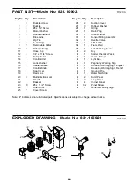
Page 20: ...22 1 Basket 23 10 8 x 1 1 2 Screw 24 1 Filter Door 25 2 Cover Screw 26 2 Suction Cover 27 3 Rubber Washer 28 1 O ring 29 1 Drain Plug 30 1 Hose Washer 31 1 Sensor Fitting Assembly 32 1 Diverter Valve...

Page 21: ...21 EXPLODED DRAWING Model No 831 105021 R1200A 4 28 5 13 29 12 3 14 9 16 16 3 9 15 1 2 2 7 17 18 26 25 20 20 31 20 27 All manuals and user guides at all guides com a l l g u i d e s c o m...

Page 22: ...22 NOTES All manuals and user guides at all guides com...

Page 23: ...23 NOTES All manuals and user guides at all guides com...

Page 24: ...from improper maintenance or any damage to the wood or tile exterior attributable to freight mishandling damage resulting from improper winterization damage to the spa shell resulting from improper c...

Reviews: