background image

GB

 | 

Operating Instructions

GB-7

Always ensure before starting the chainsaw that the 

hand protection 4 is locked in the operating position. 

To do this, pull back the hand protection  in the direc-

tion of the handle.
2. Rundown brake

In accordance with the latest regulations, this chain saw 

is equipped with a mechanical rundown brake. This brake 

is  connected  to  the  chain  brake  and  stops  the  running 

chain after the chain saw has been switched off. 
It  is  activated  by  releasing  the  ON/OFF  switch.  The 

rundown  brake  avoids  injuries  through  the  coasting  of 

the chain.

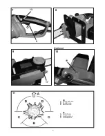
3. Chain catch bolt  

(Fig. 9) 

This chainsaw is fitted with a chain catch bolt (17). If the 

chain breaks when the saw is in operation, the chain bolt 

will catch the loose chain end and thus prevent injury to 

the operator‘s hand.

Optional

4. Overloading protection 

(Fig. 10)

Your  chain  saw  is  designed  with  a  overload  protection 

with  circuit  breaker.  If  the  chain  saw  is  clogged  (e.g. 

blocking of the cutting blade, blade teeth jammed, over-

load cutting) during cutting operation, the overload circuit 

breaker will cut the mains power supply automatically to 

protect your chain saw. 

NOTE:

 The circuit breaker will be activated when 

cutting current is over 35-40 A, and it can be reset 

manually through press reset button (18) after 30s 

cooling completely. 

Instructions  on  working  properly  with  the 

chain saw

 (Fig. 11 - 17)

a) Felling a Tree

When bucking and felling operations are being performed 

by two or more persons, at the same time, the felling op-

eration should be separated from the bucking operation 

by a distance of at least twice the height of the tree being 

felled. Trees should be felled in a manner that would en-

danger any person, strike any utility line, the utility com-

pany should be notified immediately.
The  chain  saw  operator  should  keep  on  the  uphill  side 

of the terrain as the tree is likely to roll or slide downhill 

after it is felled.
A retreat path should be planned and cleared as neces-

sary befor cuts are started. The retreat path should ex-

tend back and diagonally to the rear of the expected line 

of fall as illustrated in Figure 11.
Before felling is started, consider the natural lean of the 

tree, the location of larger branches and the wind direc-

tion to judge which way the tree will fall.
Remove dirt, stones, loose bark, nails, staples, and wire 

from the tree where felling cuts are to be made.

b) Notching Undercut 

Make the notch 1/3 the diameter of the tree, perpendicu-

lar  to  the  direction  of  fall  as  illustrated  in  11.  Make  the 

lower horiziontal notching cut first. This will help to avoid 

pinching of either the saw chain or the guide bar when the 

second notch is being made.

c) Felling Back Cut 

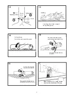
Make the felling back cut at least 2 inches (50 mm) higher 

than  the  horizontal  notching  cut  as  illustrated  in  Figure 

12.  Keep  the  felling  back  cut  parallel  to  the  horizontal 

notching cut. Make the felling back cut so enough wood 

is left to act as a hinge. The hinge wood keeps the tree 

from twisting and falling in the wrong direction. Do not cut 

through the hinge.
As the felling cut gets close to the hinge the tree should 

begin to fall. If there is any chance that the tree may not 

fall in the desired direction or it may rock back and bind 

the saw chain, stop cutting before the felling back cut is 

complete and use wedges of wood, plastic or aluminum 

to open the cut and drop the tree along the desired line 

of fall.
When the tree begins to fall remove the chain saw from 

the cut, stop the motor, put the chain saw down, then use 

the retreat path planned. Be alert for overhead limbs fall-

ing and watch your footing.

d) Limbing a Tree 

Limbing  is  removing  the  branches  from  a  fallen  tree. 

When limbing, leave larger lower limbs to support the log 

off the ground. Remove the small limbs in one cut as il-

lustrated in Figure 13. Branches under tension should be 

cut from the bottom up to avoid binding the chain saw. 

e) Bucking a Log 

Bucking  is  cutting  a  log  into  lengths.  It  is  important  to 

make sure your footing is firm and your weight is evenly 

distributed on both feet. When possible, the log should be 

raised and supported by the use of limbs, logs or chocks. 

Follow the simple directions for easy cutting.
When  the  log  is  supported  along  its  entire  length  as  il-

lustrated in Figure 14, it is cut from the top (over-buck).
When the log is supported on one end, as illustrated in 

Figure 15, cut 1/3 the diameter from the underside (un-

derbuck). Then make the finished cut by overbucking to 

meet the first cut.
When the log is supported on both ends, as illustrated in 

Figure 16, cut 1/3 of that diameter from the top overbruck. 

Then make the finished cut by underbucking to meet the 

first cut.
When  bucking  on  a  slope  always  stand  on  the  uphill 

side of the log, as illustrated in Figure 17. When “cutting 

through”, to maintain complete control release the cutting 

pressure near the end of the cut without relaxing your grip 

on the chain saw handles. Don’t let the chain contact the 

ground. After completing the cut, wait for the saw chain 

to stop before you move the chain saw. Always stop the 

motor before moving from tree to tree.

Maintenance and Servicing

Always  withdraw  the  plug  when  carrying  out 

maintenance and servicing.

Summary of Contents for EKSN 2000-40 WK

Page 1: ...Operating Instructions Translation of the original Operating Instructions Read operating instructions before use GB EKSN 2000 40 WK Vor Inbetriebnahme Gebrauchsanweisung lesen DE Gebrauchsanweisung O...

Page 2: ...connecteur 15 Strain relief 16 Knurling wheel for quick chain tension adjustment 12 7 8 5 6 1 4 2 10 9 11 13 3 14 15 16 1 DE 1 lsichtfenster 2 Vorderer Handgriff 3 ltankverschluss 4 Vorderer Handschut...

Page 3: ...2 5 3 mm 4 1 2 A B 6 16 8 7 B A 3 _...

Page 4: ...3 8 2 4 17 9 10 18 13 9 7 Optional 11 GB A Felling direction B Danger area C Escape area DE A F llrichtung B Gefahrenzone C Fluchtbereich...

Page 5: ...the log 2 1 2 1 Cut from the top Don t let the chain contact the ground Then make the finished cut by overbucking to meet the first cut Cut 1 3 the diameter from the underside Cut 1 3 of that diameter...

Page 6: ...afety a General safety instructions b Instructions on using the chain saw safely c Warning to the danger of recoil kickback d Instructions on safe working techniques Starting up GB 5 1 Filling the oil...

Page 7: ...the provi sions of the German Product Safety Act Model EKSN 2000 40 WK Rated Voltage V 230 240 Nominal Frequency Hz 50 Fuse time lag A 16 Rated Output W 2000 Guide Bar mm 405 Cutting length mm 380 Cha...

Page 8: ...t you are doing and use common sense when operating a power tool Do not use a power tool while you are tired or under the influence of drugs alcohol or medi cation A moment of inattention while operat...

Page 9: ...sap lings The slender material may catch the saw chain and be whipped toward you or pull you off balance Carry the chain saw by the front handle with the chain saw switched off and away from your body...

Page 10: ...ents 21 If the chain saw comes into contact with earth stones nails or other foreign objects withdraw the plug immediately and check the chain as well as the bar 22 Ensure that no chain oil penetrates...

Page 11: ...T screw 7 Then turn the knurling wheel upwards direction of arrow Tension the chain such that it can be lifted by about 3mm in the middle of the bar as shown in Fig 4 3 Connecting the chainsaw Fig 5 W...

Page 12: ...1 Make the lower horiziontal notching cut first This will help to avoid pinching of either the saw chain or the guide bar when the second notch is being made c Felling Back Cut Make the felling back c...

Page 13: ...sales service Chain does not run Check position of handguard see ill 8 Chain only runs if handguard brake is released Sparks fly at the motor Motor or carbon brushes damaged Take the chain saw to a s...

Page 14: ...been respected EN 60745 1 2009 A11 EN 60745 2 13 2009 EN 55014 1 A1 2009 EN 55014 2 A2 2008 EN 61000 3 2 A2 2009 EN 61000 3 3 2008 Engineering type licence No BM 501 96980 0001 T V Rheinland LGA Produ...

Page 15: ...it a Allgemeine Gefahrenhinweise b Hinweise zum sicheren Betrieb der Kettens ge c Hinweise zur R ckschlaggefahr d Hinweise zur sicheren Arbeitstechnik Inbetriebnahme DE 6 1 ltank f llen 2 Montage von...

Page 16: ...lt wichtige Hinweise die Maschine sicher sachgerecht und wirtschaftlich zu betreiben und damit Gefahren zu vermeiden Reparaturen und Ausfallzeiten zu vermindern und die Zuverl ssigkeit und Lebensdauer...

Page 17: ...trischen Schlages d Zweckentfremden Sie das Kabel nicht um das Ger t zu tragen aufzuh ngen oder um den Ste cker aus der Steckdose zu ziehen Halten Sie das Kabel fern von Hitze l scharfen Kanten oder s...

Page 18: ...it anderen Elektrowerkzeugen verwendet werden Der angegebene Schwingungsemissionswert kann auch zur Einsch tzung von erforderlichen Arbeitspausen verwendet werden Der angegebene Schwingungsemissionswe...

Page 19: ...chienen und S geketten Falsche Ersatzschienen und S geketten k nnen zum Rei en der Kette und oder zu R ckschlag f hren Halten Sie sich an die Anweisungen des Her stellers f r das Sch rfen und die Wart...

Page 20: ...n l bekommen Sie berall im Fachhandel Verwenden Sie kein Alt l Dies f hrt zur Besch digung Ihrer Kettens ge und zum Verlust der Garantie Zum F llen des ltanks ziehen Sie bitte den Netz stecker ffnen S...

Page 21: ...k hlung wird der berlastschutz wieder aktiviert der Kette das R ndelrad nach unten Pfeilrichtung drehen Zum Schluss die Knebelschraube 7 von Hand fest anziehen Die Kettenspannung hat gro en Einfluss a...

Page 22: ...nbereich ber den geplanten Fluchtweg verlas sen Auf herunterfallende ste achten und nicht stolpern d Entasten Hierunter versteht man das Abtrennen der ste vom gef llten Baum Beim Entasten gr ere nach...

Page 23: ...g der Anschlusslei tung dieses Ger tes darf diese nur durch eine vom Hersteller benannte Reparaturwerkstatt oder vom Werkskundendienst ausgetauscht werden da hierf r Spezialwerkzeug erforder lich ist...

Page 24: ...LWA 105 0 dB A Konformit tsbewertungsverfahren nach Anhang V Richtlinie 2000 14 EG Das Baujahr ist auf dem Typschild aufgedruckt und zus tzlich anhand der fortlaufenden Seriennummer feststellbar M nst...

Reviews: