background image


57 

Now press the Load soft key, which will load the memory and bring you back to 
the set screen with the current memory and its parameters.  If you press the Exit 
soft key you will be brought back to memory screen, and if you press the Exit soft 
key again you will go back to the Set screen. 
 

4.4.2  Naming a Memory 

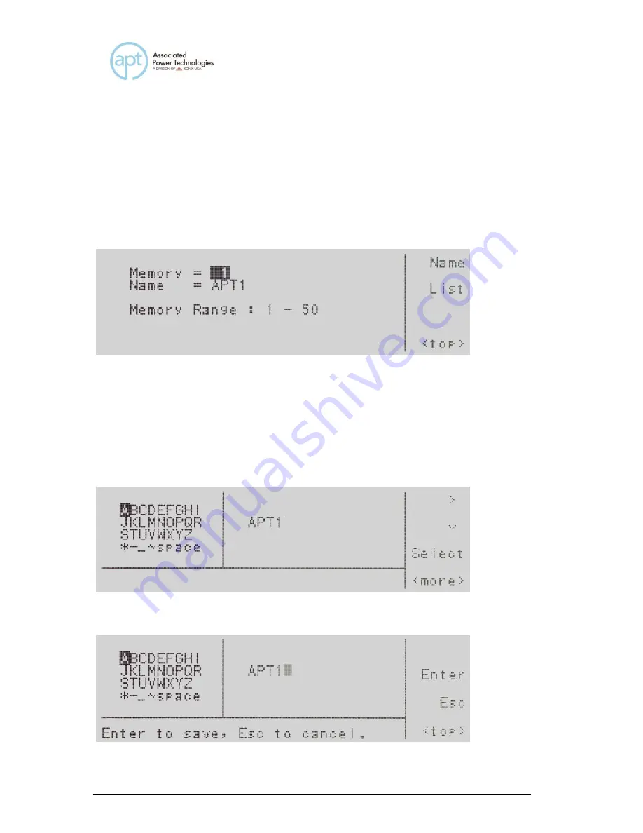
To name a memory location you will need to press the <more> soft key when in 
the memory screen. 


Now press the Name soft key.  This will bring you to the character map for 
entering the memory name.  The numeric keypad is also available for creating a 
memory name.  Press the <top> soft key to use the > soft key and 

 soft key. 

Press the Select soft key to choose your characters.  If you use the numeric 
keypad the character will be entered automatically when the keypad is pressed.  
To delete a character use the <- - key on the numeric keypad. The memory name 
can not be longer than 10 characters.  The screen will look as follows: 


Now press the <more> soft key which will bring you to the following screen: 


Summary of Contents for apt 400XAC Series

Page 1: ...400XAC Series Modular AC Power Source Operation Manual for Models 430XAC 460XAC PART 39469 Ver 1 12 January 04th 2021...

Page 2: ...000 4 11 2004 IEC 61000 4 34 2005 A1 2009 Supplementary Information The product herewith complies with the requirements of the Low Voltage Directive 2014 35 EU the EMC Directive 2014 30 EU and the RoH...

Page 3: ...Front Panel Controls 29 3 2 2 Rear Panel Controls 31 3 2 3 Soft Keys 32 4 Programming Instructions 34 4 1 Powering on the Instrument 34 4 1 1 Set Screen Description 35 4 1 2 Security 36 4 1 3 Lock 37...

Page 4: ...Trans Time PROGRAM Mode only 71 4 6 11 Editing Trans Cycle PROGRAM Mode only 71 4 6 12 Editing Ramp Up PROGRAM Mode only 73 4 6 13 Editing Timer Unit PROGRAM Mode only 74 4 6 14 Editing Delay PROGRAM...

Page 5: ...1 3 Sending and Receiving Commands 100 8 2 GPIB Interface 101 8 2 1 GPIB Connector 101 8 2 2 GPIB Address 101 8 3 Interface Functions 101 8 4 USB GPIB RS 232 Interface Command List 102 8 4 1 Basic Com...

Page 6: ...129 10 3 3 Power Up 129 10 3 4 Ethernet Card Menu 131 10 3 5 IP Setup 131 10 3 6 IP Address 132 10 3 7 Gateway IP 132 10 3 8 Subnet Mask 132 10 3 9 Device Name 133 10 3 10 MAC Address 134 10 3 11 Bar...

Page 7: ...the standard warranty period five years Ikonix USA recommends that your power source be calibrated on a twelve month cycle A return material authorization RMA must be obtained from Ikonix USA To obta...

Page 8: ...Power the vector sum of the real and reactive power components of a circuit Measured in VA volt amps Direct Current DC current that only flows in one direction Direct current comes from a polarized so...

Page 9: ...to determine how reactive and resistive a load is Reactive Power the power absorbed by capacitive or inductive elements in a circuit This power does no work Measured in VAR volt amps reactive Real Pow...

Page 10: ...1 Product Marking Symbols Product will be marked with this symbol when it is necessary to refer to the operation and service manual in order to prevent injury or equipment damage Product will be mark...

Page 11: ...entilation holes or damaging controls and switches also some chemicals may damage plastic parts or lettering Any replacement cables and high voltage components should be acquired directly from APT or...

Page 12: ...ect against injury Follow the recommendations below to ensure that instruments are handled in a safe manner Determine if the instrument can be lifted by one individual or requires additional support M...

Page 13: ...00 1500 2000 2500 3000 3500 4000 4500 0 500 1000 1500 2000 2500 3000 3500 430XAC 0 1000 2000 3000 4000 5000 6000 7000 8000 9000 0 1000 2000 3000 4000 5000 6000 7000 460 XAC Input VA Input VA Output VA...

Page 14: ...shall not interrupt the protective earth conductor 2 4 Selecting the Appropriate Wire Gauge Below is a table which provides recommended appropriate wire gauges for the 400XAC 430XAC Input L N G 12AWG...

Page 15: ...improperly rated cord For North American A UL listed and CSA labeled power cord must be used with the instrument in the United States and Canada The power cord must include a NEMA5 15 style male plug...

Page 16: ...n Description L1 L2 L3 N1 N2 N3 L N 1P2W L1 N1 L2 N2 L3 N3 A B C 3P3W L1 N1 L2 N2 L3 N3 A B C N 3P4W AC IN L3 G N2 AC IN L2 G N3 PFC1 360XAC N1 L1 AC IN G PFC3 PFC2 L 1P2W N3 L1 G N2 L2 L3 G N N1 N3 C...

Page 17: ...11 Figure 2 3 4W Configuration Wye Load Figure 3 3 3W Configuration Delta Load...

Page 18: ...12 Figure 4 1 2W Configuration Figure 5 1 3W Configuration...

Page 19: ...crew 39243 2 1 2 7 Environmental Conditions Operating Environment Temperatures 5 40 C 41 104 F Relative humidity 20 80 Altitude 2 000 meters 6 562 feet Do not block any ventilation openings to prevent...

Page 20: ...uthorization RMA number which is provided by the customer support department Failure to ship your instrument without a RMA number will result in additional fees for handling and storage APT will not b...

Page 21: ...phase 18 4A at 110V for per phase 5 300V 4 6A at 220V for per phase 9 2A at 220V for per phase Inrush Current peak 1 1 2W 5 150V 110 4A 220 8A 5 300V 55 2A 110 4A 1 3W 5 150V 36 8A for per phase 73 6A...

Page 22: ...V 300V 0 01 4 60A 0 01 9 20A Resolution 0 01 Amps Accuracy 2 0 of setting 2 counts OC Fold Back Response Time 1 4S Ramp Up Timer second 4 Range 0 0 999 9s Resolution 0 1s Accuracy 0 1 0 05 sec Ramp Do...

Page 23: ...ng 5counts at 501 1000Hz and CF 1 5 Current peak 55 2A Current peak 5 Range 0 0A 38 0A 0 0A 76 0A Resolution 0 1A Accuracy 1 of reading 5counts at 40 0 70 0Hz 1 5 of reading 10counts at 70 1 500Hz 1 5...

Page 24: ...tion 0 1Hz Accuracy 0 1Hz 501 1000Hz Accuracy 0 2Hz Voltage Range 0 0 727 5V Resolution 0 1V Calculated Formula A B C 3 Current r m s Range 15 L 0 005A 1 200A 0 005A 2 400A H 1 00A 13 00A 2 00A 26 00A...

Page 25: ...n Voltage 3 Range 5 300VAC 150 300V Auto Range Resolution 0 1V Accuracy 0 2 of setting 3counts Frequency Range 40 1000Hz Full Range Adjust Resolution 0 1Hz at 40 0 99 9Hz 1Hz at 100 1000Hz Accuracy 0...

Page 26: ...cy 0 2 of reading 3counts Current r m s 5 Range 0 05A 39 00A 0 05A 78 00A Resolution 0 01A Accuracy 1 of reading 5counts at 40 0 500Hz 1 of reading 5counts at 501 1000Hz and CF 1 5 Current peak 82 8A...

Page 27: ...600 VAC line 150 300V Auto Range Resolution 0 1V Accuracy 0 2 of setting 3counts Frequency Range 40 1000Hz Full Range Adjust Resolution 0 1Hz at 40 0 99 9Hz 1Hz at 100 1000Hz Accuracy 0 03 of setting...

Page 28: ...2 of reading 3counts Current r m s 5 Range L 0 005A 1 200A 0 005A 2 400A H 1 00A 13 00A 2 00A 26 00A Resolution L 0 001A H 0 01A Accuracy L 1 of reading 5counts at 40 0 500Hz 1 of reading 5counts at...

Page 29: ...ounts at 501 1000Hz and PF 0 5 Power Factor Range 0 1 000 Resolution 0 001 Calculated Formula W VA Power Apparent VA Range 15 L 0 0VA 120 0VA 0 0VA 240 0VA H 100VA 1300VA 200VA 2600VA Resolution L 0 1...

Page 30: ...400W 5200W Resolution L 0 1W H 1W Calculated Formula L L1 Power L2 Power H Power Factor Range 0 1 000 Resolution 0 001 Calculated Formula W VA Power Apparent VA Range 15 L 0 0VA 240 0VA 0 0VA 480 0VA...

Page 31: ...ld ON 5V 210V 14 40A 0 10 28 80A 5V 420V 7 20A 0 10 14 40A Resolution 0 01 Amps Accuracy 2 0 of setting 2 counts OC Fold Back Response Time 1 4S Ramp Up Timer second 4 Range 0 0 999 9s Resolution 0 1s...

Page 32: ...ut frequency 501 1000Hz maximum voltage deviation 40V Software LVP L When output frequency 100Hz maximum voltage deviation 5V 0 5 second When output frequency 101 500Hz maximum voltage deviation 15 0...

Page 33: ...ard for standard Ethernet GPIB Safety CE Dimension 430 W x 400 5 H x 500 D mm Weight 48kg 57kg Operation Environment 0 40 20 80 RH Why use the term Counts Associated Power Technologies publishes some...

Page 34: ...ion 10 When OC Fold ON OC Fold will work only by A phase A Hi Limit setting value but B or C phase will not determine A HI Limit if B or C phase current achieve OCP current value then OCP protection 1...

Page 35: ...cting device 2 Graphic LCD 240 x 64 Monographic LCD 3 Soft Keys Multifunctional selection keys used to select parameters select screens and edit parameters 4 Number Keypad Keys used to enter numerical...

Page 36: ...nel is locked 9 Test Reset Key Used to turn ON OFF output voltage or used to reset the instrument in the event of a failure condition 10 Test Reset LED When lit indicates output is active or when blin...

Page 37: ...ard Interface card used to control program and capture data 4 Input Terminal Power Block provides input power to the instrument Model 430XAC requires 200 240 VAC 1 47 63 Hz Model 460XAC requires 1 200...

Page 38: ...to review the results after a test System Allows you to change the instruments settings and parameters Exit Allow you to exit the current screen Name Allow you to name a memory List Allows you to see...

Page 39: ...setting Next Allows you to scroll to the next parameter setting Change Allows you to open up the parameter for changing Result Allows you to open up the results screen System Allows you to open up the...

Page 40: ...a few seconds the Initialization screen will change to the Set screen The Set screen will be displayed as follows when in PROGRAM Mode If you press the more soft key within the Set screen the soft ke...

Page 41: ...rs Description of Parameters M1 1 Memory and step location 1 0s Instrument timer for output F 60 0 Hz Frequency Ap Peak Current Set Status of instrument at the present time Possible readings are set d...

Page 42: ...isplayed The display will appear as follows You may now type in the new password using the numeric keypad Press the Enter key to accept the new password or press the Esc key to escape After you type i...

Page 43: ...ou may turn the function ON and OFF by pressing the Change soft key Press the Enter key to accept the new setting or the Esc key to cancel and return to the original setting When the Enter key is pres...

Page 44: ...OFF in the MANUAL Mode 2 Out Mode configures the instrument for AC or DC voltage output and also gives the capability to change the output for single phase or split phase 3 Single Step PROGRAM mode c...

Page 45: ...r to select a maximum voltage threshold or ceiling level when programming the output voltage in the testing parameters screen 9 V Lo Lmt MANUAL Mode allows the operator to select a minimum voltage thr...

Page 46: ...18 Mem Lock allows the operator to restrict access to memory and step locations Lock must be set to ON in order for Mem Lock to function 19 Volt Sense configures the for internal or external voltage...

Page 47: ...he Edit soft key to select the parameter The parameter will be highlighted black if it is available for editing Press the Edit soft key to open up the system parameter for editing The Exit soft key wi...

Page 48: ...tion into the next system parameter Out Mode 4 3 2 Editing Out Mode Use the soft keys to navigate to the Out Mode parameter Pressing the Edit soft key will provide the following screen Out Mode indica...

Page 49: ...r soft key To cancel the editing of the Single Step Mode press the Esc soft key When the Enter soft key is pressed the Single Step Mode is accepted and you transition into the next system parameter Al...

Page 50: ...st Range indicates the contrast range that can be programmed into the instrument Use the numeric keypad to enter in the contrast The ranges available are 1 9 where 9 is the highest contrast or the dar...

Page 51: ...ys to navigate to the Loop Cycle parameter only selectable for AC output Pressing the Edit soft key will provide the following screen Loop Cycle indicates the number of loop cycles that will be perfor...

Page 52: ...Limit Range indicates the voltage range that can be programmed into the instrument To change the voltage high limit or low limit use the numeric keypad and type the voltage value Once you type in a nu...

Page 53: ...Frequency Lo Limit Range indicates the frequency range that can be programmed into the instrument To change the frequency high limit or low limit use the numeric keypad and type the frequency value O...

Page 54: ...e range that can be programmed into the instrument To change the start angle or end angle use the numeric keypad and type the degree value Once you type in a number a shaded black box will begin blink...

Page 55: ...the results mode to ALL P F LAST To save the parameter press the Enter soft key To cancel the editing of the Results Mode press the Esc soft key When the Enter soft key is pressed the Results Mode is...

Page 56: ...vide the following screens OC Fold indicates the OC Fold Mode that is programmed into the instrument OC Fold Mode indicates the OC Fold Mode that can be programmed into the instrument The OC Fold Mode...

Page 57: ...r Mem Lock If you wish to bypass editing this parameter and move to the next parameter you can press the Prev or Next soft key 4 3 15 Editing Mem Lock Use the soft keys to navigate to the Mem Lock par...

Page 58: ...he voltage sense mode that can be programmed into the instrument The Volt Sense Modes available are INT and EXT Press the Change soft key to toggle the mode to INT or EXT To save the parameter press t...

Page 59: ...you transition into the next system parameter Auto Run If you wish to bypass editing this parameter and move to the next parameter you can press the Prev or Next soft key 4 3 18 Editing Function Use t...

Page 60: ...then SYSTEM select Function and press Edit This will allow the user to select 1 2W 3 4W or 1 3W To switch to DC mode from the main menu select more then SYSTEM select Mode and press Edit This will al...

Page 61: ...he memory location this will be blank as shown above The Memory Range indicates the valid range you can select for this parameter screen You can select 1 through 50 memory locations Two methods are av...

Page 62: ...more soft key one time The display will look as follows Next you will press the List soft key to provide a list of memories programmed into the instrument The screen will look as follows Navigation t...

Page 63: ...y screen Now press the Name soft key This will bring you to the character map for entering the memory name The numeric keypad is also available for creating a memory name Press the top soft key to use...

Page 64: ...when edited are not universal for each memory and step location The operator must edit each individual memory location and step location if multiple test routines are required 1 Start Angle PROGRAM Mo...

Page 65: ...voltage 10 Timer Unit PROGRAM Mode only determines the time increment that will be used for testing when the source is in PROGRAM Mode The operator can select between Second Minute Hour 11 Delay PROGR...

Page 66: ...d a failure will occur Ap Hi Lmt is only selectable when the source is configured for AC output 20 Ap Lo Lmt PROGRAM Mode only gives the operator the flexibility to program a minimum peak current thre...

Page 67: ...threshold or floor level If a minimum reactive power level is not reached a failure will occur Q Lo Lmt is only selectable when the source is configured for AC output 29 Trans Volt gives the operator...

Page 68: ...ing the L3 N output voltage Limits must be set for each phase in all steps PROGRAM mode only 34 Prompt PROGRAM Mode only gives the operator the flexibility to program a message unique to a particular...

Page 69: ...Trans Cycle If the Transient parameter is turned ON you will not see the testing parameters for Ramp Up Timer Unit Delay Dwell Ramp Down Step Cycle A Hi Lmt A Lo Lmt P Hi Lmt P Lo Lmt Ap Hi Lmt Ap Lo...

Page 70: ...ngle Range indicates the start angle range that can be programmed into the instrument End Angle indicates the end angle that is programmed into the instrument End Angle Range indicates the end angle r...

Page 71: ...s pressed the degree angle is accepted and you transition into the next parameter Memory Cycle If you wish to bypass editing this parameter and move to the next parameter you can press the Prev or Nex...

Page 72: ...or editing the Memory If you wish to bypass editing this parameter and move to the next parameter you can press the Prev or Next soft key 4 6 4 Editing the Step PROGRAM Mode only Use the soft keys to...

Page 73: ...de Setting the Voltage mode to Auto the system will automatically interpret the voltage range and switch to the high or low voltage output range Setting the Voltage mode to High will put the output vo...

Page 74: ...cy indicates the frequency currently programmed into the instrument Frequency Range 40 0 1000 Hz indicates the frequency range that can be programmed into the instrument To change the frequency use th...

Page 75: ...he next parameter Trans Volt If you wish to bypass editing this parameter and move to the next parameter you can press the Prev or Next soft key If the Transient parameter is turned ON additional para...

Page 76: ...Trans Site parameter only selectable for AC output Pressing the Edit soft key will provide the following screen Trans Site indicates the transient site that is programmed into the instrument Transien...

Page 77: ...king acknowledging the parameter is being changed Press the Enter soft key to accept the time or press the Esc soft key to move back to the Trans Time parameter screen When the Enter soft key is press...

Page 78: ...ically once the test starts This will continue to be active until the Trig soft key is pressed or a failure occurs If the Transient Trig Mode is OFF the Transient parameter previously programmed will...

Page 79: ...nd move to the next parameter you can press the Prev or Next soft key Parameter is only available if the Transient parameter is turned ON 4 6 12 Editing Ramp Up PROGRAM Mode only Use the soft keys to...

Page 80: ...avigate to the Timer Unit parameter Pressing the Edit soft key will provide the following screen Timer Unit indicates the timer unit mode that is programmed into the instrument Timer Unit Mode indicat...

Page 81: ...epted and you transition into the next parameter Dwell If you wish to bypass editing this parameter and move to the next parameter you can press the Prev or Next soft key 4 6 15 Editing Dwell PROGRAM...

Page 82: ...own time range that can be programmed into the instrument To change the ramp down time use the numeric keypad and type the time Once you type in a number a shaded black box will begin blinking acknowl...

Page 83: ...cycle is accepted and you transition into the next parameter A Hi Lmt If you wish to bypass editing this parameter and move to the next parameter you can press the Prev or Next soft key 4 6 18 Editing...

Page 84: ...the Esc soft key to move back to the Current Parameter screen When the Enter soft key is pressed the current is accepted and you transition into the next parameter P Hi Lmt If you wish to bypass editi...

Page 85: ...er soft key is pressed the power is accepted and you transition into the next parameter Ap Hi Lmt If you wish to bypass editing this parameter and move to the next parameter you can press the Prev or...

Page 86: ...screen When the Enter soft key is pressed the peak current is accepted and you transition into the next parameter CF Hi Lmt If you wish to bypass editing this parameter and move to the next parameter...

Page 87: ...or Parameter screen When the Enter soft key is pressed the crest factor is accepted and you transition into the next parameter PF Hi Lmt If you wish to bypass editing this parameter and move to the ne...

Page 88: ...r or press the Esc key to move back to the Power Factor Parameter screen When the Enter soft key is pressed the power factor is accepted and you transition into the next parameter VA Hi Lmt If you wis...

Page 89: ...is being changed Press the Enter soft key to accept the parameter or press the Esc key to move back to the Apparent Power Parameter screen When the Enter soft key is pressed the apparent power is acce...

Page 90: ...ging the parameter is being changed Press the Enter soft key to accept the parameter or press the Esc key to move back to the Reactive Power Parameter screen When the Enter soft key is pressed the pea...

Page 91: ...key is pressed the prompt is accepted and you transition into the next parameter Step Cycle If you wish to bypass editing this parameter and move to the next parameter you can press the Prev or Next s...

Page 92: ...t keys to navigate to the Phase Set parameter Pressing the Edit soft key will provide the following screen Phase Set indicates the Phase Setting mode for operating two instruments in a master slave co...

Page 93: ...esults The screen will look as follows If you have multiple steps linked together you will have to use the navigation soft keys in order to toggle through each step to review the results Press the Exi...

Page 94: ...outine according to the parameters currently programmed into the instrument when the Test Reset key is pressed However there is no test time associated with the MANUAL Mode The output is continuous un...

Page 95: ...will be flashing waiting for a voltage value to be entered from the numeric keypad Once the value has been typed into the instrument you must press the Enter soft key to accept the value The Esc soft...

Page 96: ...charge time The Test Reset LED flashes during this ramp down period to indicate the output is still active If you press the Meter soft key a shaded black box will highlight the meter parameters P or A...

Page 97: ...meter parameters of F A P Q CF Ap VA PF and the display will read the output on the on the right side of the display Every time the meter key is pressed it will toggle through the meter parameters If...

Page 98: ...y Knob is disabled If you press the Trig soft key you will hear a beep which is notification that the trigger has been activated for the Transient parameters that have been entered into the instrument...

Page 99: ...has been typed into the instrument you must press the Enter soft key to accept the value The Esc soft key is available to exit out of this mode and move back to the test screen The Rotary Knob on the...

Page 100: ...P Over Temperature Protection OCP Over Current Protection OPP Over Power Protection OVP Output Voltage Protection A SH Amplifier Shutdown Protection RCP Reverse Current Protection LVP Low Voltage Prot...

Page 101: ...Displayed if the amplifier is in an abnormal condition The LED indicator for the Test Reset key will be blinking 6 6 RCP Reverse Current Protection Displayed if the power source detects negative curr...

Page 102: ...alized PROCESSING Connection between PIN 5 PIN 6 Closes when test initialized and opens after test is completed 7 2 Signal Input and Remote Interlock The 400XAC Series also provides an remote input in...

Page 103: ...e memories Memory PIN 1 PIN 9 PIN 8 M1 OFF OFF ON M2 OFF ON OFF M3 OFF ON ON M4 ON OFF OFF M5 ON OFF ON M6 ON ON OFF M7 ON ON ON Remote Interlock The 400XAC is equipped with a Remote Interlock feature...

Page 104: ...Interface Signal Input port The instrument can still be used without the external interlock device as long as the Interlock Disable Key is plugged into the Remote Interface Signal Input port If there...

Page 105: ...low the instructions of the installation program to initialize the driver install NOTE The USB port acts as a USB to RS 232 converter As a result the PC will recognize the USB port as a virtual COM po...

Page 106: ...troller end of the cable 8 1 3 Sending and Receiving Commands Sending Commands When sending commands over the USB RS 232 bus the instrument will send a response string of 06 Hex or 6 decimal and Ackno...

Page 107: ...f 20 m No more than 15 device loads connected to each bus with no less than two thirds powered on For example 1 GPIB controller and a maximum of 14 GPIB instruments Note A bus extender which is availa...

Page 108: ...fter the command strings to retrieve any data from a query command The APT 400XAC series GPIB bus will not send any data to the controller without being queried The USB RS 232 bus will automatically s...

Page 109: ...420 0 V TDCURR Testing current meter See Note1 1 See Note1 1 See Note2 1 See Note2 1 A TDAP Testing current peak meter See Note4 A TDP Testing power meter See Note3 1 W TDPF Testing pf meter 0 000 1 0...

Page 110: ...en the first step test results will be found in location 3 not in location 1 Each parameter is separated by commas and includes step number test type test status and metering The syntax for this comma...

Page 111: ...ated the query will return a value of 0 for continuous 1 for Off or a range from 0 9999 cycles MEMORYCYCLE Read the value of the current memory cycle signal When the memory cycle has been activated th...

Page 112: ...106 or current EXTP External trigger pulse Trigger one pulse with relation to how the SYNC event is set...

Page 113: ...r 40 0 1000 Hz TDA VOLT Testing voltage meter 0 0 300 0 V TDA CURR Testing current meter See Note1 1 A TDA AP Testing current peak meter See Note4 A TDA P Testing power meter See Note3 1 W TDBA PF Tes...

Page 114: ...while a test is in process Query only available in AC Program mode and AC Manual mode TDC Read the selected Phase C meter values while a test is in process Query only available in AC Program mode and...

Page 115: ...REQ Testing frequency meter 40 0 1000 Hz TDL1VOLT Testing voltage meter 0 0 300 0 V TDL1CURR Testing current meter See Note1 1 A TDL1AP Testing current peak meter See Note4 A TDL1P Testing power meter...

Page 116: ...of these commands require a parameter value to be included with the command The companion query command will read the parameter The writing of the parameter requires that the unit not be included wit...

Page 117: ...X 0 1 0 L1 N 1 L2 N SDPS TRANSIENT PHASE X RAMPUP XXXX RAMP UP TIME XXXX XXX X 0 1 999 9 XXX X 0 1 999 9 s RAMPUP RAMP UP TIME 0 1 999 9 0 1 999 9 s TUNIT X TIME UNIT X X 0 2 0 Second 1 Minute 2 Hour...

Page 118: ...CFHI XX XX CF HI XX XX X XX 0 00 10 00 CFHI CF HI 0 00 10 00 CFLO XX XX CF LO XX XX X XX 0 00 10 00 CFLO CF LO 0 00 10 00 VAHI XXXX VA HI XXXX See Note3 VAHI VA HI VALO XXXX VA LO XXXX VALO VA LO QHI...

Page 119: ...OFF 1 ON SS SINGLE STEP 0 1 0 1 ALARM X ALARM X X 0 9 0 OFF 9 high ALARM ALARM 0 9 CONTRAST X CONTRAST X X 1 9 9 high CONTRAST CONTRAST 1 9 PUP X POWER UP X X 0 2 0 OFF 1 ON 2 LAST PUP POWER UP 0 2 LC...

Page 120: ...2 0 2 8 4 6 IEEE 488 2 Common Commands These commands are required by the IEEE 488 2 standard with the exception of PSC PSC Most of these commands are not available over the USB RS 232 bus except for...

Page 121: ...8 Power On ESE value Standard Event Status Enable Command value 0 255 ESE Standard Event Status Enable Query 0 255 STB Read Status Byte Query BIT 0 01H 1 All PASS BIT 1 02H 2 FAIL BIT 2 04H 4 ABORT BI...

Page 122: ...executed WAI After the command is executed it prevents the instrument from executing any further query or commands until the no operation pending flag is TRUE ESR Queries the power on status clear set...

Page 123: ...the Standard Event Enable register and Status Byte Enable registers will be cleared when power is turned ON 0 setting indicates the Enable registers will be loaded with Enable register masks from non...

Page 124: ...llivolts DC and 110 VAC 400 VDC Potentiometer Adjustment tool Oscilloscope Plastic Inductor Adjustment Tool Required Measurement Equipment 475k watt resistor 10uF 110 volt non polarized capacitor 9 2...

Page 125: ...and activate the output of the instrument 5 Adjust Inductor L3 on the OPTAC300 Output board so that the output high frequency waveform to minimum 6 Reset the output 7 Connect the output B and N of the...

Page 126: ...nt 12 Adjust VR2 on the PWMAC300 board so that the DVM measures 0 volts 10mV 13 Then set the output voltage to 110 volts in the low voltage range and activate the output of the instrument 14 Adjust VR...

Page 127: ...AC True RMS Ammeter 0 300 VAC True RMS Voltmeter Required Measurement Equipment 430XAC 112 Resistor 0 9A AC 12 Resistor 9A AC 12 7 Apeak 430XAC SmartConfig 56 Resistor 1 8A AC 60 Resistor 18A AC 25 4...

Page 128: ...del number For example if you are calibrating the 400XAC the readings will be Current 2 0A Current 36 00A Power 4000W and A Peak 52 0A Use the Select soft key to select the parameter for calibration I...

Page 129: ...soft key you will be returned to the calibration mode screen 9 10 Calibration of Voltage 300 0V Use the up or down arrow soft keys to navigate to the Voltage 300 0V parameter and press the Select soft...

Page 130: ...press the Select soft key Follow the prompt message provided on the display and press the Test Reset button to move into the calibration screen for current If you press the Exit soft key at this scre...

Page 131: ...Exit soft key at this screen you return to the calibration mode screen Enter the current reading from the ammeter with the numeric keypad When the value has been selected press the Enter soft key and...

Page 132: ...ernet port is for use with a standard CAT 5 Ethernet cable and may be connected to any compatible PC The 9 pin D type subminiature connector labeled RS232 is for connection of the APT 400XAC to an RS...

Page 133: ...ber for the Ethernet Card in TCP connections is 10001 10 3 Ethernet Card Setup In order to setup the Ethernet card the operator will need information from the local network administrator Please have y...

Page 134: ...To be completed by Network Administrator Ethernet Card Address ______ ______ ______ ______ ______ Device Name _____________________ Device IP Address _______ _______ _______ _______ Gateway IP Addres...

Page 135: ...sh a connection with the server anytime the user modifies a parameter and exits the Ethernet Card Parameters Menu or uses the command set at the end of this option description Thus if the IP Setup is...

Page 136: ...XAC to request an IP address automatically from the network to which it is connected The Ethernet Card will wait for an IP Address for approximately 20 seconds If the APT 400XAC successfully receives...

Page 137: ...400XAC will request an IP address from the server to which it is connected When AUTO is selected the APT 400XAC will attempt to automatically request an IP Address from the server upon power up To res...

Page 138: ...ress the Exit soft key to save the new settings If the IP Setup parameter is set to AUTO you do not need to enter an IP Address manually 10 3 7 Gateway IP Highlight the Gateway IP parameter using the...

Page 139: ...0 3 9 Device Name Highlight the Device Name parameter using the soft keys When the Device Name parameter is highlighted press the Edit soft key The Device Name screen will appear as follows From this...

Page 140: ...djustable 10 3 11 Barcode Input Highlight the Barcode INPUT parameter using the soft keys When the Barcode INPUT parameter is highlighted press the Edit soft key The Barcode INPUT parameter can be set...

Page 141: ...be named 123456789 When the product s barcode is scanned the APT 400XAC will immediately execute the test associated with that barcode The test file name is limited to 10 characters However if the us...

Page 142: ...me the test will be executed automatically If APT 400XAC does not find a file name that matches the barcode string the unit will beep notifying the user that it did not find a matching file name The t...

Page 143: ...137 setting...

Page 144: ...espond with the 06 hex 6 decimal Acknowledge ACK ASCII control code if the transfer was recognized by the instrument If there was an error with the command string the instrument will respond with 15 h...

Page 145: ...Settings Command Wait Times IP Mode Command Wait Time After Command is Sent Manual SIA SGA SSM 8 seconds SIM 0 14 seconds Auto SDN 14 seconds SIM 1 8 seconds Wait times are approximate and can vary ba...

Page 146: ...This is to protect the user in terms of safety and to insure a high accuracy of operation and measurement of this instrument at all times User Modification Modification by the user of the instrument...

Page 147: ...Shorting Bar for Input 3 phase 4 wire Y or 1 phase 2 wire connection Part does not include screw 39243 460XAC 39179 1 Shorting Bar for Input 1 phase 2 wire connection together with 39178 Part does not...

Page 148: ...Block 30A 3 positions 39171 1 Input Terminal Block 30A 4 positions 460XAC 39463 1 Output Terminal Block 75A 5 positions 460XAC PCB Assemblies 38967 1 KEY6700 Keypad Board 39063 1 USB RS232 USB RS232...

Page 149: ...240mm 460XAC 38808 2 Fan 24VDC 60mm 460XAC 39263 4 430XAC 5 460XAC Fan 24VDC 120mm 37923 2 F1 Fuse 2A Slow 20mm for FLY61000 and FLY61040 39180 2 F1 F2 Fuse 4A Slow 30mm for DDC61000 430XAC 39182 2 F...

Reviews: