28
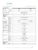
2. No load to Full load, for output frequencies of <100Hz reference the Load
Regulation (Hardware).
For output frequencies>100Hz reference the Load Regulation (Software). Output
will stabilize to ±0.5V, <1s.
3. No load
4. Between step for program mode step link :
Step by step need to spend 40ms on the same Voltage range mode.
Step by step need to spend 100ms on the different Voltage range mode.
5. Full wave loads only.
6. The DC mode has fixed Ramp-Down time of 1 second when output turns off.
7.
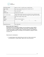
Short Condition = Load Voltage ≤ 10 volts.
8. The Software LVP protection condition need at the Dwell time >1s.
9. When OC Fold = ON, OC Fold will work only by L1 A Hi-Limit setting value, but L2
will not determine A Hi-Limit, if L2 current achieve OCP current value then OCP
protection.
10. When OC Fold = ON, OC Fold will work only by A phase A Hi-Limit setting value,
but B or C phase will not determine A HI-Limit, if B or C phase current achieve
OCP current value then OCP protection.
11. 3Ø4W, 1Ø3W, 1Ø2W also can do the Transient output and 3Ø4W, 1Ø3W can
select which one phase to do Transient output.
12. Interlock protect include hardware and software protect. Output shutdown time
<20ms
13. The high and low limit judgment function will automatically judge positive and
negative value of reactive power.
14. The reactive power meter will indicate negative calculated value when phase angle
of voltage leads phase angle of current.
15. The power measurement range will force to change from low to high when current
(r.m.s) or power measurement range in any one phase is changed from low to high.
16. The VA and Q measurement range will follow power measurement range.
0
2
4
6
0
50
100
150
C
re
s
t
Fa
c
to
r
Output Voltage %
Crest Factor vs Output Voltage %


