background image

-6-

www.igmtools.com

up the workpiece and cause kickback when the 

saw is restarted. 
• Keep saw blades clean, sharp, and with 

sufficient set. Never use warped saw blades or 

saw blades with cracked or broken teeth. Sharp 

and properly set saw blades minimise binding, 

stalling and kickback.


4.8 Table saw operating procedure warnings                                    


• Turn off the table saw and disconnect the 

power cord when removing the table insert, 

changing the saw blade or making adjustments 

to the riving knife or saw blade guard, 

and when the machine is left unattended. 

Precautionary measures will avoid accidents.


• Never leave the table saw running 

unattended. Turn it off and don’t leave the 

tool until it comes to a complete stop. An 

unattended running saw is an uncontrolled 

hazard. 


• Locate the table saw in a well-lit and level 

area where you can maintain good footing and 

balance. It should be installed in an area that 

provides enough room to easily handle the size 

of your workpiece. Cramped, dark areas, and 

uneven slippery floors invite accidents.


• Frequently clean and remove sawdust from 

under the saw table and/or the dust collection 

device. Accumulated sawdust is combustible 

and may self-ignite. 
• The table saw must be secured. A table saw 

that is not properly secured may move or tip 

over. 
• Remove tools, wood scraps, etc. From 

the table before the table saw is turned 

on. Distraction or a potential jam can be 

dangerous. 
• Always use saw blades with correct size and 

shape (diamond versus round) of arbour holes. 

Saw blades that do not match the mounting 

hardware of the saw will run off-centre, causing 

loss of control. 
• Never use damaged or incorrect saw blade 

mounting means such as flanges, saw blade 

washers, bolts or nuts. These mounting means 

were specially designed for your saw, for safe 

operation and optimum performance. 
• Never stand on the table saw, do not use 

it as a stepping stool. Serious injury could 

occur if the tool is tipped or if the cutting tool is 

accidentally contacted. 
• Make sure that the saw blade is installed 

to rotate in the proper direction. Do not use 

grinding wheels, wire brushes, or abrasive 

wheels on a table saw. Improper saw 

blade installation or use of accessories not 

recommended may cause serious injury.


4.9 Electrical 


• Machine plugs must match the outlet. Never 

modify the plug in any way. Do not use any 

adapter plugs with earthed (grounded) power 

tools. Unmodified plugs and matching outlets 

will reduce risk of electric shock. 

• Disconnect the power first. Always disconnect 

machine from power supply before adjusting, 

changing tooling, or servicing machine. 


• Power supply: 230V/50Hz/1 phase.


• Use a qualified electrician for all electrical 

connections. Failure to do so may result in 

damage to the tool and electrical shock to the 

operator and bystanders.


• Power plugs. Your machine may not come 

with a power plug because of the variance 

in power receptacles. Consult with a local 

electrician prior to purchasing a power plug.

Do not abuse the cord. Never use the cord for 

carrying, pulling or unplugging the power tool. 

Keep cord away from heat, oil, sharp edges 

or moving parts. Damaged or entangled cords 

increase the risk of electric shock. 

• Extension cords. Consult with or use a 

qualified electrician prior to sizing extension 

cords for use with this machine.  
• When operating a power tool outdoors, use an 

extension cord suitable for outdoor use. Use of 

a cord suitable for outdoor use reduces the risk 

of electric shock. 
• If operating a power tool in a damp location is 

unavoidable, use a residual current device (rcd) 

protected supply.  
• Electrical protection. End user should connect 

the machine to a circuit protected with a 16 A 

circuit breaker, tripping characteristic C (16/1/C) 

and overvoltage protection. 


4.10 Noise emissions


• 

Reference standards. 


The measurements of noise emission were 

conducted according to the EN ISO 11202:2010 

for the determination of sound pressure level 

at the operation positions. When the measured 

sound pressure levels at the operation positions 

exceed 80db(a), the measurements of sound 

power levels were conducted according to EN 

ISO 3746:2010. 
• 

Operating conditions. 


The operating conditions for noise 

measurement comply with Annex A of ISO 

7960:1995.


• 

Testing results:

A-weighted Sound Pressure - Level 91.3 dB

A-weighted Sound Power - Level 113.8 dB

Associated uncertainty - K=4dB

Background noise of measurement surrounding 

is - 55dB


The figures quoted are emission levels and 

are not necessarily safe working levels. Whilst 

there is a correlation between the emission 

and exposure levels, this cannot be used 

reliably to determine whether or not further 

precautions are required. Factors that influence 

the actual level of exposure of the workforce 

include the characteristics of the work room, the 

other sources of noise etc. i.e. the number of 

machines and other adjacent processes. Also 

the permissible exposure level can vary from 

country to country. This information, however, 

will enable the user of the machine to make a 

better evaluation of the hazard and risk. 


4.11 Grounding


• Proper grounding of your machines lowers the 

risk of injury by electricity. 


• Avoid body contact with earthed or grounded 

surfaces, such as pipes, radiators, ranges 

and refrigerators. There is an increased risk 

of electric shock if your body is earthed or 

grounded. 


• Do not modify the plug. Do not remove any of 

the prongs attached to the proper plug for the 

machine. 


• Use only 3-wire extension cords. 

Some extension cords only have two wires, 

which does not allow for grounding. 


• Always use grounded connections and work 

only on a grounded circuit. 


4.12 Rulings  


Warning: Before connecting this tool to a 

power supply (receptacle, outlet, etc.) Make 

sure that the voltage supplied is the same 

that is specified on the nameplate of the tool. 

Also make sure that the power supply is 

equipped with the appropriate breaker and 

plug according to your local electrical code. If 

in doubt, do not plug in the machine. Using this 

tool with a voltage different than that stated 

on the nameplate can damage the electrical 

components of this machine and any such 

damage will not be covered by a warranty.
Warning: Some dust created by power sanding, 

sawing, grinding, drilling and other construction 

activities contains chemicals known to cause 

cancer, birth defects or other reproductive harm. 

Some examples of these chemicals are:

• Lead from lead-based paint.

• Crystalline silica from bricks, cement, and 

other masonry products.

• Arsenic and chromium from chemically treated 

lumber. 

Your risk of exposure varies, depending on how 

often you do this type of work. To reduce your 

exposure to these chemicals, work in a well-

ventilated area and work with approved safety 

equipment, such as face or dust masks that are 

specifically designed to filter out microscopic 

particles. 


4.13 Notice on safe use 


The machinery sold by Laguna Tools, 

distributed by IGM Tools and machinery co., 

are safe when used properly and comply to 

with the CE norms, standards and regulations 

for safe use. Laguna Tools or IGM is in no 

way responsible for injury or death that occurs 

while using this product. Your personal safety is 

100% your responsibility and using this product 

requires 100% of your attention. 


If there is any concern related to the application 

you are intending to use this tool for, DO NOT 

proceed until you have contacted the retailer 

you purchased it from and have been advised 

on the correct application of the product.  

This manual is intended to thoroughly cover 

the setup up, maintenance, and proper 

adjustments of your new purchase. Aside from 

the proceeding general safety considerations, 

this manual DOES NOT cover woodworking 

or metalworking techniques that are possible 

with this product and the appropriate safety 

precautions necessary for safe practices. There 

are several organizations with published safe 

practices, techniques, and proper operation of 

this tool. 


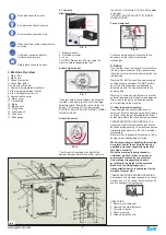
                Warning

                The symbols below advise that you  

follow the correct safety procedures when using 

this machine. 

                Keep your fingers away from the 


                saw blade 

                Environmental protection:

                Waste electrical products should not  


be disposed of with household waste.


Please recycle where facilities exist. 

Check with your local Authority or retailer for 

recycling advice. 

Summary of Contents for Laguna Fusion 3

Page 1: ...50 910 Email prodej igm cz www igm cz CEF33623003 2019 30 Table Saw Tischkreiss ge Kotou ov pila Kot ov p la K rf r szg p Pilarka tarczowa Fusion3 man_151 Fusion3_A4ob_kotoucova pila_EN DE CZ SK HU PL...

Page 2: ...is in conformity with the following directives Machinery Directive 2006 42 ES Low Voltage Directive 2014 35 ES Electromagnetic Compatibility Directive 2014 30 ES Designed in conformity with EN 1870 19...

Page 3: ...3 1 Contents Professional Square Zero Clearance Throat Plate pre installed 250 mm Saw Blade pre installed Riving Knife pre installed Mitre Gauge ships in tool holder Tool Holder pre installed Fence B...

Page 4: ...sonal Safety Stay alert watch what you are doing and use common sense when operating a power tool do not use a power tool while you are tired or under the influence of drugs alcohol or medication A mo...

Page 5: ...or a slip could direct your hand towards the saw blade and result in serious personal injury Feed the workpiece into the saw blade or cutter only against the direction of rotation Feeding the workpiec...

Page 6: ...surements of sound power levels were conducted according to EN ISO 3746 2010 Operating conditions The operating conditions for noise measurement comply with Annex A of ISO 7960 1995 Testing results A...

Page 7: ...when lifting the tool into position and moving the tool into position Warning DO NOT connect to a power supply until the setup is complete DO NOT perform any of the following steps installations or a...

Page 8: ...Rail 2 PTSF236110175 0130 127 5 Front Rail 2 PTSF236110175 0130 127 6 Hardware kit Box 3 Rear rail 1 PTSF236110175 0130 127 5 Front rail 1 PTSF236110175 0130 127 6 Pre installed on machine Throat plat...

Page 9: ...gn the entire front rail section to the blade Pic 29 9 Level and fasten front rail To level the front rail sections to the table top use a ridged straight edge atop the loosely fit rail sections Apply...

Page 10: ...nd and engage the cam lock with the thumb of your right hand 6 Reinstall the throat plate Pic 41 Grasp the pawls up and out of the way to re insert the throat plate Lock the throat plate Pic 42 CAUTIO...

Page 11: ...the fence to ensure good distance Adjust the Viewport Pic 51 Use a 2 Philips head driver to loosen but do not remove the transparent scale reader Adjust the viewport as needed tighten the screws Note...

Page 12: ...ere are 3 bolts to loosen prior to adjusting the table see step 4 4 Loosen the three table fastener bolts 5 Adjust as needed Loosen Table Bolts Pic 61 Locate and loosen right side table to cabinet bol...

Page 13: ...rforming properly If the table saw blade is slipping or is feeling underpowered you may need to tighten the belt To do so follow the steps below 1 Unplug the table saw 2 Remove the motor cover 3 Locat...

Page 14: ...A1 2009 is not lower than 20m s ensure machine can be normal exhausted User must wear dustproof mask 1 Fit the 100 mm dust hose over the dust port not included and secure in place with a hose clamp 2...

Page 15: ...alignment of the guard and splitter make sure there is clearance with the saw blade 8 3 Ripping small workpieces Do not attempt rip cuts if the work piece is too small as this will oblige you to place...

Page 16: ...Machine trips the overload or feels underpowered during operation Possible Causes 1 Feed rate cutting speed too fast 2 Workpiece material unsuitable for machine 3 Pulley sprocket slipping on shaft 4 M...

Page 17: ...ss dieses Produkt den folgenden Richtlinien entspricht Machinery Directive 2006 42 EC Low voltage Directive 2014 35 EC Electromagnetic Compatibility Directive 2014 30 EC Entworfen in bereinstimmung mi...

Page 18: ...le der Maschine Profi Tischeinlage in der Tischkreiss ge eingebaut 250 mm S geblatt in der Tischkreiss ge eingebaut Spaltkeil in der Tischkreiss ge eingebaut Winkelanschlag auf Seite der Tischkreiss g...

Page 19: ...efinden Halten Sie den Arbeitsbereich sauber und gut beleuchtet Nicht aufger umter Arbeitsbereich kann den Gebrauch der Maschine einschr nken und Verletzungen verursachen Vergewissern Sie sich dass de...

Page 20: ...aschine ein Die Maschine f hrt bessere und sicherere Arbeiten aus wenn sie mit der richtigen Geschwindigkeit betrieben wird Verwenden sie beim Arbeiten richtige Werkzeuge Machen Sie sich mit den M gli...

Page 21: ...te oder nicht standardm ige Werkst cke schneiden die keine gerade Kante haben um entlang der Anschl ge gef hrt zu werden Ein verdrehtes geknotetes oder nicht standardm iges Werkst ck ist unstabil und...

Page 22: ...hkraft Jede Besch digung des Verl ngerungskabels ist sofort zu reparieren Verwenden Sie beim Arbeiten mit der Maschine au erhalb der Werkstatt ein Verl ngerungskabel mit der entsprechenden IP Schutzkl...

Page 23: ...Auspackung Wenn durch den Transport Sch den entstanden sind notieren Sie die einzelnen Sch den auf dem Frachtbrief oder lehnen Sie die Sendung ab Rufen Sie sofort das Gesch ft an wo die Maschine gekau...

Page 24: ...erweiterung PTSF236110175 0130 4 Anm Das vordere Profil des Anschlags besteht aus zwei Teilen lang und kurz Das hintere Profil des Anschlags besteht auch aus zwei Teilen lang und kurz ANM Aus Sicherhe...

Page 25: ...dass sich der Sperrhebel in ge ffneter Position befindet Abb 30 10 Stellung der Tischkreiss ge ausgleichen Um die Stabilit t der Tischkreiss ge auszugleichen verwenden Sie zwei einstellbare F e im Unt...

Page 26: ...mus Heben des grauen Hebels den Spaltkeil ins Loch einf hren 4 Links von der Spannung einf hren Abb 39 F hren Sie den Spaltkeil vorsichtig ins Loch ein und dr cken Vergewissern Sie sich dass der Spalt...

Page 27: ...ellt wird Der Anschlag muss auf Null gesetzt werden um pr zises Schneiden gew hrleisten zu k nnen 1 Tischkreiss ge von Stromversorgung trennen 2 Anschlag an das S geblatt schieben 3 Luppe lockern 4 Na...

Page 28: ...nnen verschiedene Zubeh rteile verwendet werden mehr unter www igm cz Ok Abb 56 Multifunktionswinkel Anm Diese Methode kann auf der Tischkreiss ge Kratzer hinterlassen Besser Abb 57 Messuhr am Winkela...

Page 29: ...von 0 bis 45 Grad eingestellt werden 2 Motorabdeckung entfernen Abb 67 HINWEIS VERGEWISSERN SIE SICH DASS DIE MASCHINE NICHT ANS STROMNETZ ANGESCHLOSSEN IST Um einen einfachen Zugang zur Einstellschr...

Page 30: ...mit dem Spaltkeil verwendet werden Anm Wenn der Keilsperrhebel nicht verriegelt werden kann oder wenn er sich zu steif bewegt stellen Sie die Schraube auf der R ckseite der Verriegelung ein Dabei muss...

Page 31: ...st nach dem Ausschalten der Tischkreiss ge vom Tisch wenn es nicht gro genug ist um sicher genommen zu werden Wenn das Werkst ck zu d nn ist ist es sicherer einen verl ngerten Arm zu verwenden als das...

Page 32: ...weisungen berpr fen Sie t glich Folgendes Lockere Schrauben Besch digtes S geblatt Besch digter Spaltkeil oder S geblattabdeckung Verschlissene oder besch digte Drahten Andere Besch digungen berpr fen...

Page 33: ...eblattfehler 3 Motoraufh ngung ist locker defekt 4 Unkorrekter Zusammenbau der Maschine 5 Lockere Riemenscheibe 6 Lockerer oder verschlissener Antriebsriemen 7 Lockere oder verschlissene Riemenscheibe...

Page 34: ...nto produkt vyhovuje n sleduj c m p edpis m Machinery Directive 2006 42 EC Low voltage Directive 2014 35 EC Electromagnetic Compatibility Directive 2014 30 EC Konstruov no ve shod s EN 1870 19 2013 EN...

Page 35: ...o na pile 250 mm kotou instalov no na pile Rozv rac kl n instalov no na pile hlov prav tko na stran pily Dr ky p slu enstv instalov no na pile Pod ln prav tko Kryt kotou e Kl matice Mont n kl e Obr 1...

Page 36: ...av rozum Nepou vejte elektrick n ad ani stroj pokud jste unaven pod vlivem drog alkoholu nebo l k Chv le nepozornosti m e m t za n sledek v n zran n Pou vejte ochrann od vy Pou vejte ochrann br le Och...

Page 37: ...e proti sm ru ot en P i ez n obrobku ve stejn m sm ru v jak m se pilov kotou ot nad stolem m e doj t k zata en obrobku a va ruky do ezu Nikdy nepou vejte hlov prav tko k posuvu obrobku p i pod ln m ez...

Page 38: ...dle EN ISO 3746 2010 Pracovn podm nky Provozn podm nky pro m en hluku jsou v souladu s p lohou A normy ISO 7960 1995 V sledky testov n Hladina akustick ho tlaku A 91 3 dB V en hladina akustick ho v ko...

Page 39: ...M EN M KOLEM P ka pro zamknut Obr 9 Uzamknut pod ln ho prav tka pomoc excentru pevn zajist prav tko kdekoliv v pod ln m veden 6 Sestaven stroje D vejte pozor Stroj je velice t k Pro manipulaci se stro...

Page 40: ...nt n sou stky Obsah krabice 3 Zadn profil 1 PTSF236110175 0130 127 5 P edn profil 1 PTSF236110175 0130 127 6 Nainstalov no na stroji Stoln vlo ka PTSF236110175 0130 6 Rozv rac kl n PTSF236110175 0130...

Page 41: ...u prav tka a spojte je k sob pomoc spojovac ch trn Obr 29 9 Vlo te prav tko Vlo te na pilu prav tko p edn st a a pot zadn st P ed vlo en m prav tka na st l se ujist te e je areta n p ka v otev en pozi...

Page 42: ...mechanismu Uchopte kl n a druhou ruku si nechte volnou pro uzam en 5 Uzamkn te edou p kou Obr 40 Pevn dr te rozv rac kl n levou rukou a uzamkn te up nan kl nu palcem prav ruky 6 Vlo te zp t stoln vlo...

Page 43: ...rouby na lup pomoc k ov ho roubov ku lupu neodstra ujte Upravte lupu a dot hn te rouby POZN Pokud nesta nastaven lupy k vynulov n prav tka nahl dn te do kroku slo 8 v sekci sestaven pily Nastaven kluz...

Page 44: ...stolu 5 Upravte dle pot eby Uvoln n roubu Obr 61 Uvoln te roub na prav stran stolu a sk n nad dr kem prav tka Uvoln n roubu Obr 62 Uvoln te roub na lev stran stolu a sk n nad krytem motoru Uvoln n ro...

Page 45: ...dostate n poh n n je mo n e nen emen dostate n napnut Instrukce k napnut p su najdete n e 1 Pilu odpojte od nap jen 2 Odstra te kryt motoru 3 Najd te roub pro pravu emenu 4 Napn te nebo uvoln te pomo...

Page 46: ...asku proti prachu 1 100mm hadici nasu te na ods vac hubici a upevn te hadicovou sponou 2 Ujist te se e je hadice dn upevn na 3 Po adovan pr tok vzduchu 934 m3 h 4 Zajist te pokles tlaku ka d ho v vodu...

Page 47: ...ez n men ch obrobk Nepokou ejte se ezat pod ln pokud je obrobek p li tenk Tento druh ezu v s nut um stit ruce p li bl zko kotou e co m e znamenat v n riziko zran n P i d len u ch obrobk doporu ujeme p...

Page 48: ...oln n h del pot ebuje vym nit lo iska Stroj se b hem provozu vyp n nebo se zd e m nedostate n v kon Mo n p ina 1 Rychlost posuvu je p li vysok 2 Nevhodn materi l 3 emen prokluzuje na h deli 4 Vadn lo...

Page 49: ...prehlasujeme e tento produkt vyhovuje nasleduj cim predpisom Machinery Directive 2006 42 EC Low voltage Directive 2014 35 EC Electromagnetic Compatibility Directive 2014 30 EC Kon truovan v zhode s EN...

Page 50: ...troja Profesion lna stoln vlo ka in talovan na p le 250mm kot in talovan na p le Rozvierac klin in talovan na p le Uhlov prav tko na strane p ly Dr iaky pr slu enstva in talovan na p le Pozd ne prav t...

Page 51: ...jeho po kodenie alebo raz obsluhy Nepou vajte stroj v pr tomnosti hor av ch kvapal n alebo plynov Nepou vajte stroj v pr tomnosti hor av ch kvapal n alebo plynov Stroj vytv ra iskry ktor m u zap li pr...

Page 52: ...klinom telo p lov ho listu mus by ten ie ako hr bka rozvieracieho klinu a rka rezu p lov ho kot a mus by ir ia ako hr bka rozvieracieho klinu 4 6 Upozornenie k prvkom p ly Nebezpe enstvo nikdy sa nepr...

Page 53: ...testovania Hladina akustick ho tlaku A 91 3 dB V en hladina akustick ho v konu A 113 8dB Pridru en neistota K 4 dB Hluk na pozad 55 dB Uveden hodnoty s rovne emisi a nie s nevyhnutne bezpe n mi praco...

Page 54: ...ie pozd neho prav tka pomocou excentra pevne zaist prav tko kdeko vek v pozd nom veden 6 Nastavenie stroja D vajte pozor Stroj je ve mi a k Pre manipul ciu so strojom je potreba aspo dvoch ud Upozorne...

Page 55: ...krabice 3 Zadn profil 1 PTSF236110175 0130 127 5 Predn profil 1 PTSF236110175 0130 127 6 Nain talovan na stroji Stoln vlo ka PTSF236110175 0130 6 Rozvierac klin PTSF236110175 0130 27 250mm kot PTSF236...

Page 56: ...pojovac ch t ov Obr 29 9 Vlo te prav tko Vlo te na p lu prav tko prednou as ou a a potom zadnou as ou Pred vlo en m prav tka na st l sa uistite e je areta n p ka v otvorenej poz cii Obr 30 10 Zrovnajt...

Page 57: ...chopte klin druh ruku si nechajte vo n na uzamknutie 5 Uzamknite edou p kou Obr 40 Pevne dr te rozvierac klin avou rukou a uzamkn te up nan kl nu palcem prav ruky 6 Vlo te zp t stoln vlo ku Obr 41 Zdv...

Page 58: ...pomocou kr ov ho skrutkova a lupu neodstra ujte Upravte lupu a dotiahnite skrutky POZN Ak nesta nastavenie lupy k vynulovaniu prav tka nahliadnite do kroku slo 8 v sekcii nastavenie p ly Nastavenie kl...

Page 59: ...uvo nite 3 skrutky vi krok 4 4 Uvo nite tri skrutky stola 5 Upravte pod a potreby Uvo nenie skrutky Obr 61 Uvo nite skrutku na pravej strane stola a skrine nad dr iakom prav tka Uvo nenie skrutky Obr...

Page 60: ...ontrolova napnutie p su a celkov v kon p ly Ak kot p ly preklz va alebo sa zd e nie je dostato ne poh an je mo n e nie je reme dostato ne napnut In trukcie k napnutiu p su n jdete ni ie 1 P lu odpojte...

Page 61: ...asu te na ods vaciu hubicu a upevnite hadicovou sponou 2 Uistite sa e je hadice riadne upevnen 3 Po adovan prietok vzduchu 934 m3 h 4 Zaistite pokles tlaku ka d ho v vodu prachu ktor m r chlos pr du v...

Page 62: ...zranenia Pri delen u ch obrobkov odpor ame pou i pred en ruku alebo pod vac blok pre bezpe n pr cu 8 4 Prie ny rez Rez naprie vl knu s cie om skr ti d ky obrobku naz vame prie nym rezom S men mi aleb...

Page 63: ...hriade 9 Otestujte preto en m hriade a po koden hriade potrebuje vymeni lo isk Stroj sa behom prev dzky vyp na alebo sa zd e m nedostato n v kon Mo n pr ina 1 R chlos posuvu je pr li vysok 2 Nevhodn m...

Page 64: ...hogy ez a term k megfelel a k vetkez el r soknak G pekr l sz l 2006 42 ES ir nyelv Kisfesz lts g g pek 2014 35 ES ir nyelv EMC 2014 30 ES ir nyelv A k vetkez k ppen tervezt k EN 1870 19 2013 EN60204 1...

Page 65: ...lel haszn lat r l 3 A g p tulajdons gai 3 1 A g p sszetev i Professzion lis asztal bet t telep tve van a f r szg pen 250 mm k rf r szlap telep tve van a f r szg pen Has t k telep tve van a f r szg pen...

Page 66: ...megvil g tva A nem tiszta munkat r korl tozhatja a g p haszn lat t s s r l s oka is lehet Gy z dj n meg arr l hogy a munkat r biztons gos s nem el rhet k pzetlen szem lyek s gyerekek ltal Ha lehets g...

Page 67: ...ndig haszn ljon szor t t vagy satut ha el rhet Ezeknek haszn lata biztons gosabb mint a munkadarab k zzel t rt n tart sa Enn l a g pn l csak egy helyes adagol si ir ny van Ne tolja a munkadarabot ross...

Page 68: ...lyen egyenes fel leten kell elhelyezni A f r szg pet gy kell elhelyezni hogy elegend hely legyen a k l nb z m ret munkadarabok kezel s re A f r szg p sz k s t t s egyenetlen fel letre val helyez se s...

Page 69: ...s tv nnyal egy tt megfelelnek a g pek biztons gos haszn lat nak eur pai szabv nyainak is A Laguna Tools s az IGM v llalatok semmilyen esetben sem felel sek az ezen term k zemeltet se k zben t rt nt s...

Page 70: ...e le a l d t a raklapr l 4 Ellen rizze az sszes alkatr szt 5 T vol tsa el a v d olajt A f r szg p tv tele 11 bra Ilyen llapotban van a g p elk ldve az zletb l Csavarja ki a csavarokat a l d b l 12 bra...

Page 71: ...s az asztal bal oldali h tuls r sz n NE H ZZA MEG ER SEN Ezeket a csavarokat nem kell er sen megh zni majd csak akkor ha a profil sszes r sze r gz tve lesz 22 bra 2 Csavarja fel a vonalz h tuls hossz...

Page 72: ...szerel se 33 bra FIGYELMEZTET S GY Z DJ N MEG ARR L HOGY A F R SZG P NINCS CSATLAKOZTATVA A T PFESZ LS GRE Az asztalbet t elt vol t s ra vagy beszerel s re ki kell nyitni a reteszeket Ezut n helyezze...

Page 73: ...os kar 6 Csavarja le a tengely any j t 7 Vegye le vagy helyezze fel a k rf r szlapot FIGYELMEZTET S Gy z dj n meg arr l hogy a k rf r szlap fogai a f r szg p eleje fel mutatnak az bra szerint 2 T vol...

Page 74: ...kelt imbuszkulcsot ezt a s llyesztett nylon csavarok felemel s hez kell haszn lni ameddig nem rintkeznek a vonalz el ls profilj val H ts be ll t csavar 53 bra A hosszanti vezet vonalz igaz t sa a k r...

Page 75: ...fel let t Az asztal s a kapocs k z tegyen egy darab sz vetet vagy puha f t 2 V gezze el az els m r seket 64 bra FIGYELMEZTET S GY Z DJ N MEG ARR L HOGY A F R SZG P NINCS CSATLAKOZTATVA A T PFESZ LS G...

Page 76: ...be a sz j feszess g t A meghajt sz j cser je 1 A f r szg pet csatlakoztassa le a t pfesz lts gr l 2 T vol tson el minden asztalbet tet a k rf r szlapot s egys g kieg sz t t 3 T vol tsa el a motor bur...

Page 77: ...elk sz theti l sd az br t Figyelmeztet s Csak a gy rt ltal sz ll tott adagol t vagy a gy rt tmutat sa szerint elk sz tett kieg sz t t haszn lja Ezek az adagol k megfelel t vols got biztos tanak a kez...

Page 78: ...rja le a f r szlap v d burkolat t s v gezze el a v g st V g s ut n t vol tsa el a lev gott darabokat 88 bra Figyelmeztet s A g mb ly munkadarab sz g alatti v g sakor fontos a munkadarab forg s nak meg...

Page 79: ...zn ljon cs kkentse az el retol s sebess g t s a v g s magass g t 9 Ellen rizze hiba eset n cser lje ki 10 ll tsa be a sz j feszess g t cser lje ki 11 Ellen rizze jav tsa ki cser lje ki 12 K sse be hel...

Page 80: ...jszej instrukcji obs ugi jest zgodny z nast puj cymi przepisami Machinery Directive 2006 42 EC Low voltage Directive 2014 35 EC Electromagnetic Compatibility Directive 2014 30 EC Zaprojektowany zgodni...

Page 81: ...ny Profesjonalna wk adka sto owa zainstalowana na pile Tarcza 250 mm zainstalowana na pile Klin rozszczepiaj cy zainstalowany na pile Przyk adnica k towa z boku pi y Uchwyty na akcesoria zainstalowane...

Page 82: ...perator maszyny Utrzymuj powierzchni robocz w czysto ci oraz dobrze o wietlon Nieczysto ci w obszarze roboczym mog ograniczy prawid owe dzia anie maszyny i spowodowa obra enia Upewnij si e miejsce pra...

Page 83: ...obr bk drewna i metalu obrabiany przedmiot powinien by zabezpieczony za pomoc odpowiednich zacisk w i imade Zawsze u ywaj zacisku lub imad a Korzystanie z nich jest znacznie bezpieczniejsze ni trzyma...

Page 84: ...ofa dowanych tarcz lub tarcz ze z amanymi z bami Ostre i precyzyjne narz dzia minimalizuj ryzyko odrzutu i niedok adno w ci ciu 4 8 Ostrze enia zwi zane z bezpiecze stwem podczas pracy z pilark Zawsze...

Page 85: ...cz stotliwo ci wykonywania tego rodzaju pracy Aby zmniejszy nara enie na negatywne dzia anie chemikali w nale y pracowa w dobrze wentylowanym pomieszczeniu i pracowa z zatwierdzonymi i atestowanymi ak...

Page 86: ...przed ewantualnymi uszkodzeniami Maszyna powinna by przechowywana w temperaturze otoczenia 25 55 C Podczas transportu i przechowywania uwa aj aby nie wystawia maszyny na deszcz ani nie uszkadza opakow...

Page 87: ...zmontowane bezpo rednio przez u ytkownika Przed monta em przeczytaj poni sze zalecenia Rys 16 Os ona tarczy tn cej Rys 17 5 M8x1 5 podk adka podk adka nakr tka Rys 18 5 ruba z bem kwadratowym 8x1 5 po...

Page 88: ...s po lewej stronie mo na kontrolowa blokad k podczas przesuwania pi y Rys 31 11 Przymocuj maszyn do pod o a Za pomoc rub przymocuj maszyn do pod ogi Rys 32 6 5 Instalacja usuwanie wk adki sto owej 1 O...

Page 89: ...ENIE UPEWNIJ SI E PI A NIE JEST POD CZONA DO R D A ZASILANIA Po wyj ciu wk adki i otwarciu mechanizmu blokuj cego podnosz c szar d wigni w klin rozszczepiaj cy do otworu 4 Przesu w lew stron od mechan...

Page 90: ...51 Za pomoc rubokr ta krzy akowego poluzuj ruby lupy nie wyjmuj lupy Wyreguluj lup i dokr ruby UWAGA Je li ustawienie lupy nie jest wystarczaj ce do zresetowania przyk adnicy przejd do kroku 8 w rozd...

Page 91: ...tkowym pomiarem St dostosuj zgodnie z potrzebami Przed przyst pieniem do regulacji najpierw odkr trzy ruby patrz krok 4 4 Poluzuj trzy ruby sto u 5 W razie potrzeby odpowiednio dostosuj Poluzowanie ru...

Page 92: ...acji nachylenia Delikatnie dokr rub 5 Dostosuj wed ug potrzeby Rys 70 Znajd rub przeznaczon do regulacji nachylenia Delikatnie dokr rub 6 Dostosuj skal wed ug potrzeby Rys 71 Na obudowie maszyny wyreg...

Page 93: ...ci nienia dla ka dego wylotu py u kt ry ma pr dko przep ywu powietrza 1500Pa 5 Przep yw powietrza urz dzenia odci gowego m s trociny suche 20 m s zawarto wody r wna si 18 mokrych trocin 28 m s Ostrze...

Page 94: ...ia lub mier OSTRZE ENIE Nigdy nie przybli aj adnej cz ci cia a do obracaj cej si tarczy tn cej Po zako czeniu ci cia wy cz pi i poczekaj a tarcza ca kowicie si zatrzyma 8 2 Ci cie wzd u ne pod k tem R...

Page 95: ...ub wydaje si e ma s absz wydajno Mo liwa przyczyna 1 Zbyt du a pr dko posuwu 2 Niew a ciwy materia 3 Pasek lizga si na wale 4 Wadliwe o yska silnika 5 Wadliwy stycznik 6 Przegrzany silnik 7 Obrabiany...

Page 96: ...d bezpo rednim kontaktem minimalnie ochron IP2X 3 Wszystkie ods oni te cz ci przewodz ce powinny by pod czone do ochronnego obwodu po czeniowego 4 Zamknij i zablokuj obudow maszyny OSTRZE ENIE 1 W cel...

Page 97: ...www igm cz Wiring Diagram Fusion F3 230V Schaltungsdiagramm Fusion F3 230V Diagram zapojen Fusion F3 230V Diagram zapojenia Fusion F3 230V Bek t si rajz Fusion F3 230V Schemat po czenia Fusion F3 230...

Page 98: ...ww igm cz Fence assembly Schema einzelner Teile Diagram sou stek Diagram s iastok Alkatr sz rajz Schemat cz ci Parts diagram Sestaven prav tka Zostavenie prav tka A vonalz sszeszerel se Monta przyk ad...

Page 99: ...99 www igm cz Mitre gauge blade guard Winkelanschlag S geblattabdeckung hlov prav tko kryt kotou e Uhlov prav t ko kryt kot a Sz g vonalz a k rf r szlap v d burkolata Przyk adnica k towa os ona tarczy...

Page 100: ...100 www igm cz Motor and trunnion Motor und Aufh ngung Motor a zav en Motor a zavesenie A motor s f ggeszt se Silnik i zawieszenie...

Page 101: ...101 www igm cz Cabinet Schrank Sk Skri a G ph z Obudowa...

Page 102: ...102 www igm cz Cabinet motor Schrank Motor Sk motor Skri a motor G ph z motor Obudowa silnik...

Page 103: ...101 Round Head Self Tapping Screw M5 0 8P 8 5 45 250780 615 Connector 1 46 174716 156 Arbor Stoper 1 47 280260 901 Spring 1 48 010206 000 Retaining Ring ETW 9 2 49 000303 104 Pan Head Screw M5 0 8P 1...

Page 104: ...2 143 006001 033 Flat Washer 6 7 16 1 0t 2 144 008603 100 Square Nut M6 1 0P 10B 5H 2 145 012002 005 Key 4 4 12 2 147 130368 903 Bushing 1 148 001901 101 SET Screw Nylock M5 0 8P 5 1 156 361251 905 Pa...

Reviews: