background image

33

Relay Test Function

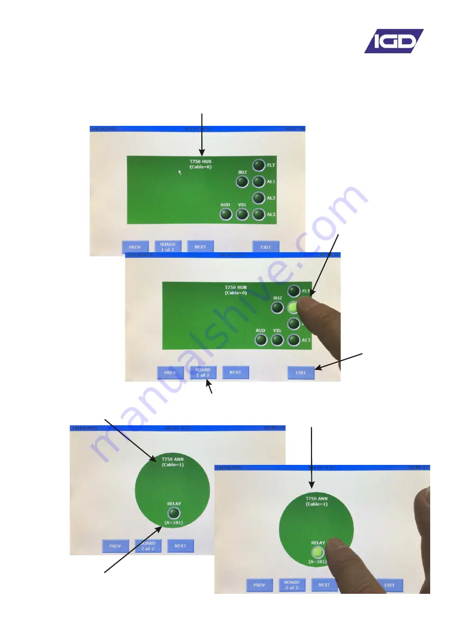
The Tocsin750 has the option to run a relay test function. Select the option and the following 
screen is displayed.

Note the outputs on the hub card are always indicated first

Select the relay to test to 
see it change its state

Use the NEXT and PREV buttons to select the desired relay 
board.
There are also screen displays for individual ‘module’ outputs.

Use EXIT to 
return to the 
main menu and 
release all 
selected relays 
back to normal 
operation.

Aelay Address

Cable Highway

Summary of Contents for TOCSIN 750 Series

Page 1: ...B a s e d D e t e c t o r C o n t r o l P a n e l O p e r a t i o n a n d M a i n t e n a n c e V 3 6 1 Triton House Crosby Street Stockport SK2 6SH England T el 44 0 161 483 1415 Fax 44 0 161 484 234...

Page 2: ...Function Test The Alarms Tab The Alarm Relay Setup Menu Calibration Menu Tab The Sensor ZERO Function The Sensor CALIBRATE Function Connection Possibilities Module PCB setup Pellistor Settings and Mo...

Page 3: ...etween 25 C and 60 C If stored at low temperatures and then brought into a warmer environment care should be taken to ensure that condensation does not form or enter critical electrical components for...

Page 4: ...d more frequently and should be assessed based upon exposure 7 Full Colour Touch Screen 800 x 480 1 LEL 1 Vol 0 1 Vol 1 ppm 0 1ppm Modbus Up to 128 Devices on single hub max 350 input channels includi...

Page 5: ...xic gases or Oxygen requirements and tests for apparatus using software and or digital technologies Excluding requirements for SIL Electrical equipment for measurement control and laboratory use EMC r...

Page 6: ...llers can have internal or external battery backup 2 System devices connect using 2 core cable there is no polarity requirement for the highway cabling 3 Use room status indicators to protect entry wa...

Page 7: ...detectors when zeroing and calibrating Incorrect application of gases can affect calibration results 3 Use equipment and gases traceable to a national standard Any calibration will only be as good as...

Page 8: ...lange 300W Versions have active ventilation and must be surface mounted allowing 100mm clearance all round Note that the rear case can be rotated to allow 20mm entries to face either up or down Note c...

Page 9: ...e and or damage to system components 2 WIRE SYSTEMS 2 W i r e G a s D e t e c t i o n S y s t e m I n s t a l l e r s G u i d e V x x OLIVER IGD Triton House Crosby Street Stockport SK2 6SH England T...

Page 10: ...r Battery Backup Ethernet Rs485 Remote Modbus etc Display Colour HMI Display TOC 650 2x8 LCD Fault Relay Alarm Relay 1 Alarm Relay 2 Alarm Relay 3 Direct Beacon Sounder O P Inputs for E stops Fire 4 o...

Page 11: ...se DOWN BUTTON UP BUTTON Each Addressable relay card must have its own unique base address This can be set on the card and is indicated below The relays are then addresses numbered from that base addr...

Page 12: ...nalogue and digital inputs that can be used to read data onto the system from external devices Setup of the inputs type range addressing etc is controlled via IGD s Android Apps Wiring options are ind...

Page 13: ...Relay Output DVM Test Point DVM Test Point Housing Sealing Environment Temperature Voltage Communication Relay Digital Output Digital Input Analogue I P Pellistor Port Sounder Display Comm Port 1 2 3...

Page 14: ...EMORY MAP ADDRESSES COMMAND STRUCTURE Parameter Setting 1 Modbus Mode RTU Mode Only 2 Operating Mode Slave Mode Only 1 3 Response Time Maximum 100mS 5s for Zero Command 4 Requests Maximum 32 per Secon...

Page 15: ...1 AL2 Bit2 AL3 Bit3 Fault Bit4 Sensor Disabled Bit5 Sensor Fault Bit6 Under Range Fault Bit7 Over Range Fault Bit8 Comms Fault Bit9 Spare Bit10 Spare Bit11 Spare Bit12 Spare Bit13 AL1 Muted Bit14 AL2...

Page 16: ...riod the system goes into normal monitoring operation Click on a displayed channel number to make it the currently viewed channel or type in the channel number of interest Note that the display centre...

Page 17: ...ble Fault Relay Active Alarm Relays Normal Modbus State Available Fault Relay Active Alarm Relays Normal Modbus State Available Fault Relay Active Alarm Relays Normal Modbus State Available Fault Rela...

Page 18: ...rm you must be below the alarm level Bar Graph Alarm Level Indicators Rising Latching Alarm Level Note Latching Alarms Stay Active After The Gas Level Has Gone and Must be Physically Reset Falling Lat...

Page 19: ...the system into inhibit mode Initially this will be for 60 minutes and can be terminated by selecting cancel at any time During inhibit mode the system is not communicating to its detectors and so wil...

Page 20: ...dbus State Available Fault Relay Active Alarm Relays Normal Modbus State Available Fault Relay Active Alarm Relays Normal Modbus State Available Fault Relay Active Alarm Relays Normal Modbus State Ava...

Page 21: ...ct communication 3 Perform a RELAY FIND this will set up the correct number of system relays Note that the relay sequence cannot be moved around in the same manner that the sensors can and MUST be pro...

Page 22: ...or Diagnostics Full diagnostics for the chosen detector Sensor Check Sensor diagnostic Health Check Relay Channels Change the number of system relays Relay FIND use to Find addressable relays Relay Di...

Page 23: ...NSOR CHECK PROGRAM EXIT EXIT The Tocsin 920 operating system has two access levels for set up and maintenance functions The basic menu layout is indicated on the diagram below CODE 345 MENU when engin...

Page 24: ...possible for each channel as AL1 AL2 and AL3 The type of alarm is also setup in this menu as one of either RISING ALARM RISING LATCHING ALARM FALLING ALARM FALLING LATCHING ALARM Alarm on rising gas l...

Page 25: ...isable a channel Select gas FLAMM CO CO2 etc Enter the UNITS to display LEL ppm Vol etc Enter the hub cable number that this detector is installed onto Note the first hub is cable numbers 1 to 4 Note...

Page 26: ...ype etc This will speed channel set up but it should be noted that performing a FIND and auto install will erase all the existing set up information including alarm levels and alarm action types Selec...

Page 27: ...ge of channels you wish to test and then how many communication cycles to run the test for typically 1000 When sensor test is selected the following diagnostic screen is displayed The display shows ei...

Page 28: ...outs i e detector did not respond quickly enough to request for data from Tocsin 750 Note that the overall percentage error rate should be less than 0 5 Anything greater than this is indicative of a...

Page 29: ...o Date Cal Volts Cal Date Type Range Gas Address Cable Software Serial No Prod Date Recorded Zero Voltage from last successful zero normally 1 0V 0 1V Applicable for T102A V3 00 or previous Date of la...

Page 30: ...always be reported found as Relays 1 to 4 on the hub card Relay 5 Visual SSR Output Relay 6 Audible SSR Output Relay 7 Hub Card Sounder Output Total number of relays found Select Save to install the...

Page 31: ...s connected detectors To run the test select the range of relays you wish to test and then how many communication cycles to run the test for typically 1000 When relay test is selected the following di...

Page 32: ...ctor did not respond quickly enough to request for data from Tocsin 750 Note that the overall percentage error rate should be less than 0 5 Anything greater than this is indicative of a problem requir...

Page 33: ...utputs on the hub card are always indicated first Select the relay to test to see it change its state Use the NEXT and PREV buttons to select the desired relay board There are also screen displays for...

Page 34: ...system Set alarm levels to default values If alarm devices output contacts or alarm signal outputs are provided as part of continuous duty gas detection equipment and are intended to operate when a po...

Page 35: ...rs for example From sensor channel 1 To sensor channel 6 to activate this relay on alarm Up to 7 sensor groups can be defined in this way Note in all cases that for these groups of sensors the relay w...

Page 36: ...te a particular sensor The expected sequence will be Select CALIBRATE SENSOR function Select the channel to CALIBRATE Flow calibration gas at the sensor and allow to stabilise Select to CALIBRATE Obse...

Page 37: ...s Tap on the channel number to type in the channel number if known Procedure for check reaction time to gas Ensure detector is at zero 1 LEL Use standard IGD professional gas introduction kit with 2M...

Page 38: ...NC 0V mA Apply zero gas to the detector It is important that the detector zero point is correctly set It must be considered that there is the possibility that the gas to be detected is already present...

Page 39: ...ibration gas Note that with calibration there is more to consider than with Zeroing The type and age of the detector can have an influence so it is recommended that periodically as well as calibrating...

Page 40: ...ess can be set from which all other module addresses will sequentially follow This is described later in this manual Device addresses indicated in the table are typical but can be individually set Max...

Page 41: ...ilable on the TOC 750 module PCB Please note that failure to observe and make correct connections or exceed ratings may result in damage to the PCB Ribbon Cable Connection For TOC 750 Annunciator Disp...

Page 42: ...ing systems to install and power the control panel first and then use one port on the 750 to connect and check devices prior to installing them In this manner all addresses and module set up options c...

Page 43: ...ding what is selected will determine what is then displayed for each option on the left The picture below shows the opening screen for the module PCB setup The module PCB shown graphically on the righ...

Page 44: ...NO2 etc Change of Units Add a Tag Line to the Sensor to describe location etc Options available for the IO Inputs allow Change of Unit Address Change of Range Change of Gas Type Typically CO CO2 NO2...

Page 45: ...Add a Tag Line to the Sensor to describe location etc Relay Settings and module options Display Settings and module options IO1 Settings Set as Enabled or Disabled Display Settings as Disabled Display...

Page 46: ...the detector address to display up to 4 characters to display for the gas type and units of measurement The example below shows the first available address programmed with detector address 5 gas as P...

Page 47: ...el to force and then enter the required value With the correct channel and value displayed selecting enter will force that level onto the selected channel for 30 seconds This allows testing of the ala...

Page 48: ...up then the as shipped backup will already be saved This is indicated in the screen display shown above This setup can then be restored at any point by selecting Restore Shipped If the setup has been...

Page 49: ...nternal battery backup the following battery care is recommended Installation The batteries will come pre installed but will be disconnected to prevent battery drain They should be connected before th...

Page 50: ...if is to be part of a larger monitoring system BMS etc Selecting th eModbus option from the System Settings tab gives access to modify these settings A modbus diagnostic feature is also included such...

Page 51: ...nly or M2M SIM card The SIM card must be valid for the chosen service provider The GSM module is a factory fit module Note that the GSM module utilises the RS485 modbus port Enable the Modem option Se...

Page 52: ...r provided with the SIM card or can be found via the internet or provider help desk Changing these settings is under password control normally configured by the commissioning engineer Typical Settings...

Page 53: ...as required Screen 4 allows you to select which of the entered numbers or addresses is active or disabled Screen 5 is used to select which SMS or email address accounts gets a Gas Values report This...

Page 54: ...rms Alarms Muted Alarms Reset Faults Calibrations Note the interval can be selected and the time Screen 7 is used to select which SMS or email address accounts gets a Sensor Check report Sensor check...

Page 55: ...e selected and the time Screen 9 allows selection to enable selected SMS users interaction with the system To use these features requires training from IGD to fully understand implications of taking e...

Page 56: ...tic functions are available to test the function of the GSM system as follows Select to reset the modem Select to reinitialize the modem Send a test Text Send test email Receive test SMS Force out sam...

Page 57: ...Software Option USB Port Panel Alarm Sounder 7 Colour Touch Screen RELAY 1 12 I O 1 12 HW 1 HW 3 HW 2 HW 4 POWER IN HMI Alarm relay outputs SPCO Highway Connections 1 to 4 Not used if key switch fitte...

Page 58: ...ions in out Digital Input Port 9 Digital Input Port 20 Digital Input Port 10 Digital Input Port 19 I O Ports Channels 2 thro 10 13 thro 20 Analogue 4 20mA input 0 100 LEL by default Note these ports a...

Page 59: ...6 IN8 IN4 IN9 IN5 IN7 IN3 IN2 HW1 HUB HW2 IN1 RLY2 RLY4 RLY7 RLY3 RLY6 RLY5 RLY8 RLY1 1 1 2 1 1 1 1 2 3 4 3 4 5 6 7 8 9 10 11 12 12 4 4 2 2 3 3 101 102 103 104 12 12 11 10 9 8 7 6 5 101 102 103 104 10...

Page 60: ...alog Inputs Powered from the right hand side IO Relay Card The 11 18 Rear Panel Analog Inputs Powered from the left hand side IO Relay Card IN 10 IN6 IN8 IN4 IN9 IN5 IN7 IN3 IN2 L2 L1 SCR HW1 Relay L2...

Page 61: ...Break glass units call points etc To Next Detector Node Guidance only refer to 2 Wire systems installers guide for full details Note connector orientation All connectors viewed from rear panel 1 2 3 4...

Page 62: ...ower supply Connect power supply Panel failure Please contact IGD No response to the gas Electrical Fault Please contact IGD Inaccurate indication Damaged sensor Please contact IGD Sensor fault indica...

Page 63: ...ter Disk 5110101 Remote Gassing Port 5134601 40mm Stop Button 5138601 Collector Cone Ring Lock 5138701 T103 Splash Guard 5138801 Collector cone kit MK6 TOC GLAND M20 Snap fit cable glad 5925801 Univer...

Page 64: ...ernational Gas Detectors Ltd Triton House Crosby Street Stockport Manchester United Kingdom SK2 6SH Tel 44 0 161 483 1415 E mail sales internationalgasdetectors com Website www internationalgasdetecto...

Reviews: