background image

iFLOW HVAC INC.

www.iflowhvac.com

9

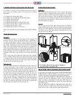
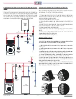
4. Suitable applications: Choosing the right heat source

The iFLOW air handler can be installed with various types of 

heat sources and heating systems. The following are its primary 

applications:

1. Air handler with tankless water heater

2. Air handler with conventional thank-type water heater

3. Air handler with heating boiler

4. Air handler with combi boiler

5. Air handler with heat pump + tankless water heater

6. Air handler with heat pump + tank-type water heater

7. Air handler with heat pump + boiler

8. Air handler with heat pump + combi boiler

Refer to the installation manual for diagrams of each type of installati-

on.                                                                              

Hybrid Heating System

Definition:


A hybrid heating system is a dual-energy system using gas OR 

electricity. The most common hybrid systems use a combination of 

a furnace and heat pump to heat and cool a home. They can be a 

fuel-saving alternative to traditional heating systems using only a 

gas furnace. Hybrid systems use outdoor conditions to automatically 

adjust to the most efficient method of heating, gas OR electricity. 

Heat pump systems operate on electricity and are significantly more 

energy efficient when compared to gas-operated furnaces. The heat 

pump is effective alone at low temperatures close to 20 degrees 

Fahrenheit. At that point, a gas furnace will kick in and help heat the 

home.

You can save money with a heat pump. Heat pumps are an excellent 

source of energy-efficient heat for your home, with the added benefit 

of cooling your home in the summer months. With significant savings 

over electric heat, heat pumps can reduce your energy bill without 

changing the comfort level in your home.

Defrost cycle:

When the ambient temperature outside gets very cold (close to 0°C 

or below) the moisture in the air freezes on the outdoor unit's heat 

exchanger as the fan blows the air across it. A heat pump has a cycle 

called a “defrost cycle,” which removes the frost from the outdoor coil. 

A heat pump unit will defrost regularly when frost conditions occur. 

The defrost cycle should be long enough to melt the ice, and short 

enough to be energy-efficient. When a heat pump goes into defrost 

mode, the heat pump shifts temporarily into the cooling mode to 

reverse the flow of refrigerant through the coils. The reversing valve 

activates and runs the refrigerant backward. Instead of extracting 

heat from the outdoor air and putting it into the house, it extracts heat 

from the house and sends it into the cold outdoor air.

iFLOW Hybrid heating System:

Definition: 

The iFLOW Hybrid Heating System Control uses a dual-energy 

system that uses gas AND electricity at the same time. This heating 

system combines an iFLOW Hydronic Air Handler, using any water 

heat source and a heat pump. It has the capability of running both at 

the same time. The air heated as it passes across the hydronic coil 

and the heat pump evaporator coil. The evaporator coils sit on top of 

the iFLOW hydronic air handler. 

Benefit: 

The main benefit of the iFLOW Hybrid Heating System is its ability to 

provide variable capacity heat, which is sufficient to provide the total 

heat loss of a house regardless of the heat pump capacity. Therefore, 

the defrost cycle will be long enough to melt the ice, and short 

enough to be energy-efficient.

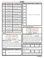
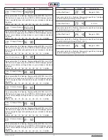
SMART MODE / SMART TEMPERATURE CONTROL MODE

In the General Parameters Setting Mode, the SMART MODE/SMART 

TEMPERATURE CONTROL MODE can be selected to provide the 

functions of the Smart Temperature Control without a thermostat. 

When the SMART MODE/SMART TEMPERATURE CONTROL is 

selected, the return air temperature sensor in the air handler will 

sense an average air temperature from the space NOT the room air 

temperature where the thermostat is located. This will provide better 

control and comfort.  

When the SMART MODE/SMART TEMPERATURE CONTROL is 

selected the blower is always active while using this function. The 

blower will run at the continuous blower speed setting selected.

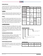
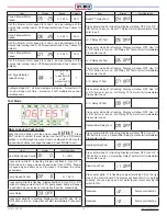
* The DH Evap Defrost Sensor must be installed on 

   the suction pipe to operate for H/P.

DH Evap Defrost Sensor

A / C Evap T. Sensor

Summary of Contents for iFLH-14000W

Page 1: ...NTELLIGENT SMART IoT TECHNOLOGIES iFLOW HYDRONIC AIR HANDLER NEW GENERATION OF HEATING COOLING iFLOW AHU MANUAL WiFi ZONING Model iFLH 14000W iFLH 16000W iFLH 18000W iFLH 16000D iFLH 18000D iFLH 18000...

Page 2: ...tankless tank water heater 12 7 Electrical requirements and making connections 12 8 Temperature sensors 12 9 Installing the iFLOW air handler with a Navien tankless water heater 13 10 Zone damper 13...

Page 3: ...rom all system components and piping prior to start up It is recommended to install purge valves between the air handler and water heater s isolation valves If connected to domestic piping creating an...

Page 4: ...n any direction Circulating Pump All air handlers require a field supplied single speed or 3 speed pump to be controlled by the iFLOW circulator control This the speed of the pump increases or decreas...

Page 5: ...ol Fan ON delay Fan OFF heat purge control 5 DHW priority dual mode heating and DHW High low limit safety control air temperature sensor Home freeze protection low ambient temperature sensor Evaporato...

Page 6: ...r the homeowner and at the same time reduces cooling loads and operating costs 3 Equipment selection and sizing iFLOW air handlers are available in 3 models Please use the following charts to determin...

Page 7: ...apacity Ton 1 2 1 5 3 2 4 Cabinet Size W x D x H in 14 x 18 3 4 x 27 1 8 16 x 20 3 4 x 27 1 8 18 x 25 3 4 x 29 1 8 mm 356 x 476 x 689 406 x 527 x 689 457 x 654 x 740 Material Cold Roll Steel Sheet Met...

Page 8: ...28 218 33 572 35 724 37 429 41 357 3 7 33 625 36 256 38 524 41 162 46 456 5 7 140 32 865 39 218 41 625 43 843 48 379 3 7 38 245 42 367 45 412 48 235 53 971 5 5 150 37 536 45 075 47 536 50 327 55 485 3...

Page 9: ...the outdoor coil A heat pump unit will defrost regularly when frost conditions occur The defrost cycle should be long enough to melt the ice and short enough to be energy efficient When a heat pump go...

Page 10: ...with all local state provincial and national code requirements that apply to the installation of this equipment The air handler must be installed in such a way that electrical components are protected...

Page 11: ...heated by the same boiler make up water and low loss header optional Sensor Installation A C Evaporator Temperature Sensor Air outlet on the Evaporator coil See Installation Illustration Page 12 Zone...

Page 12: ...minal block 7 Route low voltage thermostat wire to the unit connect to thermostat terminal on control board 8 Re secure the front access panel 8 Temperature sensors The iFLOW air handlers come equippe...

Page 13: ...W AHU at the thermostat connector Connect the communication cable from the iFLOW AHU to the cascade communication port on the Navien Water Heater Panel The parameter P28 of the NAVIEN TL WH should be...

Page 14: ...age the pump and open the purge valve Verify proper flow direction inlet valve should become warm before the outlet Close the purge valve once flushing is complete Operate the pump for 5 minutes immed...

Page 15: ...pening Ratio 0 Fully Closed 100 Fully Opened Display Description Explanation Blower Motor Speed Indicates present operation as a percentage of the total fan motor capacity Pump Speed Indicates present...

Page 16: ...tate Zone 2 Return Damper Opening Ratio 0 Fully Closed 100 Fully Opened Zone 2 Return Temperature Zone 2 Return Air Temperature in F Zone 3 Supply Damper State Zone 3 Supply Damper Opening Ratio 0 Ful...

Page 17: ...ency Set Up Anti Stagnation 0 24 Hours 24 CSA B214 requires pump circulation once every 24 hours default Some jurisdictions may require a shorter time interval based upon local codes ex if the pump mu...

Page 18: ...re there is a demand for domestic hot water For cool future function Heating Parameter Mode How to access Heating Parameter Push the mode button until the screen reads Press ENT enter to confirm Heati...

Page 19: ...3 Zone 2 Blower Speed Heating Mode 0 100 25 Set the blower motor speed for zone 2 as a percentage of the home s total heat loss or CFM requirement see Zone 1 above for details Item Display Range Defau...

Page 20: ...enter to exit Flow Switch Test Press enter while 11 is flashing Jumper terminals FS on the right side of the control board The display will flash ON if it is working correctly You can also open a hot...

Page 21: ...supply damper will open close as you increase or decrease the value OPEN 90 80 70 60 50 40 30 20 10 CLOSE Zone 3 Return Damper Test Press enter while 19 is flashing Display will flash OPEN Use UP or...

Page 22: ...lator The circulating pump is water lubricated and should not require regular maintenance The system control has a pump exercise function during prolonged periods of no heat to avoid seizing Blower Th...

Page 23: ...3 Wiring Diagrams SZ Field Installation Wiring Diagram SINGLE ZONE Wiring Diagram Do not connect A C with thermostat to the thermostat connector on the control board A C must be connected to A C conne...

Page 24: ...iFLOW HVAC INC www iflowhvac com SZ Field Installation Wiring Diagram 24 See Details Page 29...

Page 25: ...c com 25 DZ Field Installation Wiring Diagram DOUBLE ZONE Wiring Diagram Do not connect A C with thermostat to the thermostat connector on the control board A C must be connected to A C connector of c...

Page 26: ...iFLOW HVAC INC www iflowhvac com DZ Field Installation Wiring Diagram 26 See Details Page 29...

Page 27: ...ac com 27 QZ Field Installation Wiring Diagram QUAD ZONE Wiring Diagram Do not connect A C with thermostat to the thermostat connector on the control board A C must be connected to A C connector of co...

Page 28: ...iFLOW HVAC INC www iflowhvac com QZ Field Installation Wiring Diagram 28...

Page 29: ...NTROL BOARD A C CONDENSING UNIT CONTROL BOARD A C CONDENSING UNIT O C B Y1 C Y2 It should be connected O or B depending on H P type CONTROL BOARD It should be connected O or B depending on H P type CO...

Page 30: ...iFLOW HVAC INC www iflowhvac com 4 Ladder Diagram 30...

Page 31: ...against corresponding temperature sensor chart If out of range replace sensor Heat Exchanger 020 H ex Freeze Protection Ambient Temperature below 40 F Resolution Unit will automatically run circulato...

Page 32: ...Damper Abnormal 122 Supply Zone 3 Damper Abnormal 123 Supply Zone 4 Damper Abnormal 124 Return Zone 1 Damper Abnormal 125 Return Zone 2 Damper Abnormal 126 Return Zone 3 Damper Abnormal 127 Return Zon...

Page 33: ...ecessary The pump exercise function will help prevent pump seizing Pump is noisy at start up Air is present in the loop If the noise has not diminished after 1 minute purge air in accordance with star...

Page 34: ...iFLOW HVAC INC www iflowhvac com 34 3 Component Assembly Diagram and Parts Lists Assemble Diagram...

Page 35: ...0016LC00A iFLH 160000 0018LC00A iFLH 180000 6 1 Left Panel Heat Exchange Guide 0014LG00A iFLH 140000 0016LG00A iFLH 160000 0018LG00A iFLH 180000 6 2 Left Panel Hole Support 0000LS00A iFLH 14 16 18000...

Page 36: ...ront Cover 0014FC00A iFLH 140000 0016FC00A iFLH 160000 0018FC00A iFLH 180000 2 CTL Board Assembly 30CBA0SZ iFLH 140000 30CBA0DZ iFLH 160000 30CBA0QZ iFLH 180000 3 Blower Assembly 201408CW iFLH 140000...

Page 37: ...1 2 Blower Assembly Fan 201408BF 201608BF 201808BF 2 Blower Assembly Bracket 2014081B iFLH 140000 2016091B iFLH 160000 2018101B iFLH 180000 3 Blower Motor 2016121A iFLH 14 160000 2018341A iFLH 180000...

Page 38: ...Model Remark 1 Heat Exchanger 1014004A iFLH 140000 1016004A iFLH 160000 1018004A iFLH 180000 2 A C Eva Temp Sensor 30ETS01B 3 Air Supply Temp Sensor 30ATS01B 4 Air Supply Temp Sensor Bracket 30ATB00A...

Page 39: ...d panel 30CBP0SZ 2 SZ Control Board Assembly 30CBA0SZ 3 Transformer 402420B 4 Terminal 400T001B 5 Motor Power Cable 50121EON 16AWG 6 Blow Motor Control Cable 50MCTL1A 7 Circulator Control Cabel 50PCTL...

Page 40: ...d panel 30CBP0SZ 2 DZ Control Board Assembly 30CBA0SZ 3 Transformer 402420B 4 Terminal 400T001B 5 Motor Power Cable 50121EON 16AWG 6 Blow Motor Control Cable 50MCTL1A 7 Circulator Control Cabel 50PCTL...

Page 41: ...d panel 30CBP0SZ 2 QZ Control Board Assembly 30CBA0SZ 3 Transformer 402420B 4 Terminal 400T001B 5 Motor Power Cable 50121EON 16AWG 6 Blow Motor Control Cable 50MCTL1A 7 Circulator Control Cabel 50PCTL...

Page 42: ...iFLOW HVAC INC www iflowhvac com 42 4 Installation Diagram iFLOW EZEE Plumbing Kit and iFLOW Stand...

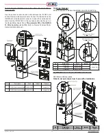
Page 43: ...iFLOW HVAC INC www iflowhvac com 43 Installation on the wall...

Page 44: ...iFLOW HVAC INC www iflowhvac com 44...

Page 45: ...15 60EPFO4A 1 7 Tee with Valve Return 60EPFO5A 1 8 Air Vent 1 2 60EPFO6A 1 9 AHU Inlet Tee Union 60EPFO7A 1 10 Circulator Tee Union w Check Valve 60EPFO8A 1 11 Circulator Grundfos UPS15 58RU 60EPFO9A...

Page 46: ...eating Application Tankless water Heater DHW Expansion Tank Circulator with Check Valve Heat Pump Check Valve An Scald Valve Cold Water Flow Switch Outdoor Sensor Air Purge Valve Circulator with Check...

Page 47: ...Check Valve An Scald Valve Cold Water Flow Switch DHW AHU with Tankless Water Heater Space Heating Application Air Purge Valve AHU with Tank Water Heater Space Heating Application Air Elliminator Expa...

Page 48: ...nkless Boiler Space Heating Application AHU with Combi Boiler Space Heating Application Boiler Make up Water Feeder Air Elliminator Circulator Expansion Tank Tankless Combi Boiler Cold Water DHW Make...

Page 49: ...ombi Boiler Space Heating Application Expansion Tank Circulator with Check Valve Circulator with Check Valve Cold Water Make up Water Feeder Tankless Combi Boiler Expansion Tank Circulator with Check...

Page 50: ...r contrary to the instructions included with this unit at the time of shipment or failure to perform maintenance as detailed in aforementioned instructions This warranty will not cover normal maintena...

Page 51: ...lowhvac com INSTALLATION OPERATION MANUAL iFLOW AIR HANDLER Version 8 6 December 12 2019 CONFORMS TO UL STANDARD 1995 CERTIFIED TO CSA STANDARD C22 2 NO 236 iFLOW HVAC INC 29 Howden Road Toronto ON L3...

Reviews: