iFLOW HVAC INC.
www.iflowhvac.com
12
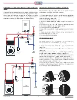
6) Installing the iFLOW air handler with a tankless/tank water
heater:
Check with the tankless water heater manufacturer prior to installation
to ensure it can be used for combo space heating applications. Make
sure to check that the valves, including but not limited to the purge
and isolation valves are properly installed. If connecting to a tankless
water heater, the circulating pump needs to be sized correctly.
7) Electrical requirements and making connections:
This unit requires single phase AC 120V power to operate and must
be hardwired. To connect, follow these directions:
1. To avoid electrical shock, turn off electrical power at the breaker
dedicated to the air handler. Ensure the power remains off while any
wiring connections are being made.
2. Remove the iFLOW front access panel.
3. Route the field supplied line voltage wiring to the iFLOW air
handler.
4. Using CSA & UL listed wire nuts, connect the field supplied wires
to the air handler (black to black and white to white).
5. Connect ground wire to GND terminal.
6. Repeat the process for the circulating pump (connect to terminal
block).
7. Route low voltage thermostat wire to the unit; connect to
thermostat terminal on control board.
8. Re-secure the front access panel.
8) Temperature sensors:
The iFLOW air handlers come equipped with 5 wire sensors that plug
into connectors on the control board for easy servicing.
1. Supply water sensor: mounted on the supply end of the water
heating coil.
2. Return water sensor: mounted on the return end of the water
heating coil.
3. Supply air sensor: mounted above the water heating coil exchanger
to detect supply air temperature and freezing temperatures.
4. Outdoor temperature sensor: modulates air handler operation
based on outdoor temperature. Provides outdoor reset function.
5. Return air sensor: factory installed in return air path blower. If you
install a slab coil on the return air side, you must install the return air
sensor before(or upstream of) the slab coil.
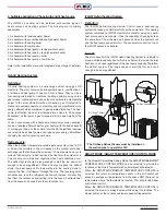
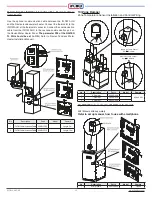
6. A/C Evap sensor: mount on the A coil, or on the slab coil. It should
be installed on the surface of the cold air outlet on the evaporator or
the U-bend pipe. Refer to the figure below.
Air
Elliminator
Expansion
Tank
Circulator
with
Check Valve
Flow
Switch
Check
Valve
Tank
Water Heater
D H W
An
�
Scald
Valve
Cold
Water
An
�
Scald
Valve
Tankless
Water
Heater
Circulator
Expansion
Tank
Flow
Switch
Check
Valve
D H W
Cold
Water
Air
Elliminator
Summary of Contents for iFLH-14000W
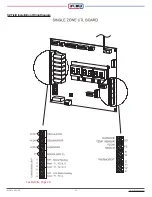
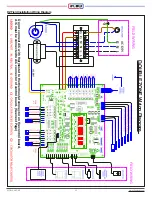
Page 24: ...iFLOW HVAC INC www iflowhvac com SZ Field Installation Wiring Diagram 24 See Details Page 29...
Page 26: ...iFLOW HVAC INC www iflowhvac com DZ Field Installation Wiring Diagram 26 See Details Page 29...
Page 28: ...iFLOW HVAC INC www iflowhvac com QZ Field Installation Wiring Diagram 28...
Page 30: ...iFLOW HVAC INC www iflowhvac com 4 Ladder Diagram 30...
Page 43: ...iFLOW HVAC INC www iflowhvac com 43 Installation on the wall...


