iFLOW HVAC INC.
www.iflowhvac.com
33
2) Problem and Solutions
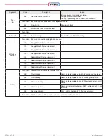
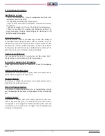
Insufficient or no heat:
• Filter or coil may be dirty. Refer to maintenance section for filter
replacement and coil cleaning.
• Air trapped in the heating loop. Purge system.
• Inlet and outlet connections to air handler are backward. Reverse
connections.
• Supply temperature is set too low. Check the water temperature.
• There is a restriction in the heating loop. Remove restriction. The
check valve may be stuck. Valves may be too restrictive or left
partially closed after purging.
Pump does not run:
Close the isolation valve on the return leg and open the drain port
so that water flows through the pump; this may free the pump. The
circulator may allow you to remove the front screw-on plate and rotate
the shaft one turn with a slotted screwdriver. If either method fails to
free the pump, removal for cleaning or replacement is necessary. The
pump exercise function will help prevent pump seizing.
Pump is noisy at start-up:
Air is present in the loop. If the noise has not diminished after 1
minute, purge air in accordance with start-up procedure.
Fan runs for cooling but not for heating:
Check thermostat connections or thermostat. Check A/C condensing
unit.
Heating during standby mode:
Probable cause is thermal syphoning. See check valve description for
details. Repair or replace the check valve.
Freeze Protection:
This feature is initiated by extremely low air temperatures and is
detected by the ambient air sensor.
Water Coil freeze protection:
This feature is initiated by extremely low air temperatures crossing
over the freeze protection sensor located above the hydronic heating
coil.
Cooling Lockout:
This feature is initiated after three freeze protection cycles occur
within a single cooling cycle, or if three freeze cycles occur when a
cooling cycle is not in progress. A freeze protection cycle is when the
air handler A/C coil freeze sensor is triggered by unacceptably low
discharge air temperature.
Summary of Contents for iFLH-14000W
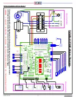
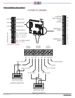
Page 24: ...iFLOW HVAC INC www iflowhvac com SZ Field Installation Wiring Diagram 24 See Details Page 29...
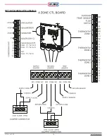
Page 26: ...iFLOW HVAC INC www iflowhvac com DZ Field Installation Wiring Diagram 26 See Details Page 29...
Page 28: ...iFLOW HVAC INC www iflowhvac com QZ Field Installation Wiring Diagram 28...
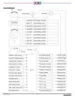
Page 30: ...iFLOW HVAC INC www iflowhvac com 4 Ladder Diagram 30...
Page 43: ...iFLOW HVAC INC www iflowhvac com 43 Installation on the wall...


