iFLOW HVAC INC.
www.iflowhvac.com
11
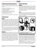
3) Installation examples:
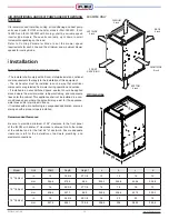
The iFLOW air handler is multi-positional and therefore can be
mounted in any position. If installed with air conditioning, proper
positioning of the evaporator coil and drain line must be considered to
install correctly.
Vertical Installation
Horizontal Installation
The evaporator coil must be installed on the supply side of the air
handler.
Hanging Installation
Ceiling Installation
4) Water Heater / Boiler Piping:
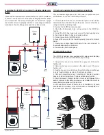
When installing the iFLOW air handler with a heating boiler or combi-
boiler in a closed loop system, refer to the boiler manufacturer’s
instructions for proper installation with an air handler. Depending on
the boiler selected and system design, it may be required to use a
primary/secondary piping arrangement to de-couple the flow through
the boiler from the flow through the air handler.
Air-removal device:
Provisions shall be made for the removal of air in the heat-distribution
piping system. The air-removal device shall be located in the area
of the heat-distribution piping system where the air is likely to
accumulate (often the highest point in the system).
Required Components:
Expansion tank, isolation valves, air eliminator, dirt collector/filter/
strainer (if other heating loads are being heated by the same boiler),
make-up water and low loss header (optional).
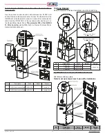
Sensor Installation
A/C Evaporator Temperature Sensor:
Air outlet on the Evaporator
coil
(See Installation Illustration: Page 12)
Zone Air Temperature Sensor:
Zone supply side: Air outlet of the damper
Zone return side: Air inlet of the damper (if there is a dedicated return
duct with the damper)
5) Domestic Piping:
Notes: When installing the iFLOW air handler with a water heater,
refer to the manufacturer’s guidelines on coupling the water heater
with an air handler. Use components and piping that are allowable
with potable use. Lead-free solder must be used on all joints.
When both top and side connections are present on the water heater,
the side connections should be used for the space-heating loop.
The heating loop connections should be positioned horizontally in a
vertical section of the domestic water line for both the inlet and outlet.
Refer to the piping diagram for details. Minimize the distance and
piping between the water heater and the iFLOW air handler.
If the main water line has an installed check valve, a potable
expansion tank must be installed to provide room for the expansion
of water.
AHU with
Case Coil or A Coil
Evaporator
Temperature
Sensor position
Filter Rack
Filter Rack
Minimum 6inch
Filter Rack
Filter Rack
Minimum 6inch
Evaporator
Temperature
Sensor position
AHU with
Slab Coil
AHU with
Case Coil or A Coil
Support
Anti-Vibration Pad
The Threaded Rod
Spring
Flat washer
Nut
Summary of Contents for iFLH-14000W
Page 24: ...iFLOW HVAC INC www iflowhvac com SZ Field Installation Wiring Diagram 24 See Details Page 29...
Page 26: ...iFLOW HVAC INC www iflowhvac com DZ Field Installation Wiring Diagram 26 See Details Page 29...
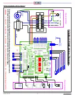
Page 28: ...iFLOW HVAC INC www iflowhvac com QZ Field Installation Wiring Diagram 28...
Page 30: ...iFLOW HVAC INC www iflowhvac com 4 Ladder Diagram 30...
Page 43: ...iFLOW HVAC INC www iflowhvac com 43 Installation on the wall...


