background image

www.ies-synergy.com

User Manual 

DIM016199-EN

17

Starting up


I

WARNING

RISK OF ELECTRIC SHOCK, INJURY, AND/OR BURNING

Make sure no vehicle is connected before starting up the charger.

Failure to follow these instructions can result in death or serious injury

Turn the disconnecting device to the position “I ON” to power up the charger.

The charger displays its name after a startup phase represented by “...” :

...

XS20 Keywatt Combo

Chademo DC Charger

Choose the charging mode

with the STOP button

Combo 2 selected

Confirm with the START button


Combo 1 selected

Confirm with the START button

CHAdeMO selected

Confirm with the START button


GB selected

Confirm with the START button

Summary of Contents for Keywatt 19

Page 1: ...UserManual Keywatt 19Trolley www ies synergy com DUM016199 EN_V002b ...

Page 2: ...your own personal noncommercial use all or part of this document on any medium whatsoever without permission of IES Synergy given in writing You also agree not to establish any hypertext links to this document or its content IES Synergy does not grant any right or license for the per sonal and noncommercial use of the document or its content except for a non exclusive license to consult it on an a...

Page 3: ...e 11 6 Handling and storage instructions 12 Storage 12 Transport 12 7 Installation 13 Visual inspection 13 Installation rules 13 Plug connections 14 AC input connector 14 DC output connector 15 8 Charger operation 16 Front panel 16 Rear Panel 16 Starting up 17 Charge with COMBO 1 or COMBO 2 connector 19 Charge with CHADEMO connector 23 Charge with GB connector 26 Charge error messages 29 Emergency...

Page 4: ...ymbol to avoid possible injury or death I DANGER DANGER indicates an imminently hazardous situation which if not avoided will result in death or seri ous injury I WARNING WARNING indicates a potentially hazardous situation which if not avoided can result in death or seri ous injury I CAUTION CAUTION indicates a potentially hazardous situation which if not avoided can result in minor or mod erate i...

Page 5: ...e aims to provide informations needed for installation use and end of life of the charger Keywatt 19 Trolley This guide must be read in integrality with others related documents This guide is intended for users of the charging station Document scope This guide concerns the following charging station Art N TROLLEY 19KW DC CHARGER Related documents Document title Reference User Manual DUM016199 EN S...

Page 6: ...HOCK INJURY AND OR BURNING Only qualified trained and authorized people will repair replace or adjust this equipment Do not let a child play near the product This charger may only be used on a non flammable surface such as concrete or similar Do not open the front cover at any time while input power is present Do not operate the unit while the cabinet door is opened or unlocked Do not use this pro...

Page 7: ...9 EN 7 4 Overview Externalview 1 2 3 4 5 6 7 Position Description 1 Start button 2 Stop button 3 Display 4 Cord bracket 5 Indicator light 6 Indicator light 7 Emergency stop button Note May change depending on version or technical modification ...

Page 8: ...M016199 EN 8 Internal doorview 1 2 3 4 5 Position Description 1 DC output Harting connector 2 Ethernet socket 3 USB socket 4 AC input Harting connector 5 Mains input switch Note May change depending on version or technical modification ...

Page 9: ...sulation protection Class IEC6103 Class II 2500VAC Min Internal DC Output Output voltage VDC _max 500 VDC Max VDC _min 200 VDC Min Output current IDC _max 60A 1 2 Max IDC _min 1A Min Max Output Power POUT 19kW Max Output connector charging station side Swapped vehicle cable Car Plug coupler COMBO1 COMBO2 CHAdeMO GB Output cable length 4 Meters Internal DC output protection Hardware and software sh...

Page 10: ...low by fans IP54 without air filter Noise 1m all direction Db A 65dbA 1m Climatic Environment constraints Operating temperature with derating 20 C to 40 C 3 Storage temperature 40 C to 70 C Relative humidity without condensation RH 10 to 95 Installation altitude Alt 2 000m Max Norms standards EC Low voltage EC directive LVD 2014 35 EU EC Electromagnetic Directive EMC 2014 30 EU Electric vehicle co...

Page 11: ...www ies synergy com User Manual DIM016199 EN 11 Compliance ...

Page 12: ... storage check the state of the charging station packaging regularly Do not store the charging station for more than a year without powering it up to avoid the deterioration of non energized electronic components Transport Throughout the transport phase take all necessary measures to keep the pallet stable NOTICE RISK OF DAMAGE TO THE CHARGING STATION Improper storage or handling may cause damage ...

Page 13: ...e charging station if it is surrounded by a wall This free space is mandatory for charging station s ventilation Never blockair flow 40cm 40cm 4 0 c m Note All pertinent state regional and local safety regulations must be observed when installing and using this device Note The manufacturer cannot be held responsible for failure to follow the instructions given in this instruc tion sheet NOTICE PRE...

Page 14: ...ous injury AC input connector Use the AC input cable ref FLPLA012536 for this equipment 5 wire plug MENNEKES AM TOP 32A 3P N T 400V plug 4m FLPLA012536 If the power cable is damaged it must be replaced with a new cable I WARNING HAZARD OF ELECTRIC SHOCK OR DAMAGE TO THE CHARGING STATION To protect against electric shocks in the event of a fault make sure that the protective earth conductor of the ...

Page 15: ...is on may cause death A cord extension set or second cable assembly or adaptator must not be used in addition to the coupler cable assembly for the connection into the vehicle Failure to follow these instructions will result in death or serious injury Output cable and connector types are COMBO 1 Output cable 4m FLPLA015693 6m FLPLA015180 COMBO 2 Output cable 4m FLPLA015491 6m FLPLA012681 CHADEMO O...

Page 16: ...cted to the product with USB or ethernet socket must be SELV Safety Extra Low Voltage and Limited Power Sources less than 15VA and meeting the requirements of Chapters 2 2 and 2 5 of IEC60950 1 2005 A1 2010 A2 2013 and N60950 1 2006 A11 2009 A1 2010 A12 2011 A2 2013 Mains input switch is not a safety isolating switch ...

Page 17: ...death or serious injury Turn the disconnecting device to the position I ON to power up the charger The charger displays its name after a startup phase represented by XS20 Keywatt Combo Chademo DC Charger Choose the charging mode with the STOP button Combo 2 selected Confirm with the START button Combo 1 selected Confirm with the START button CHAdeMO selected Confirm with the START button GB select...

Page 18: ...ircuit breakers 3 phase input circuit breaker RCD breaker and 12 24 V supplies cir cuit breaker are in upper position if not put them back to upper position using a flat head screwdriver to access the switches 5 Reinstall the access cover 6 Tighten the T25 fastening screws of the circuit breaker access cover 7 Reconnect the cables to the charger 8 Check that the charger starts If it is still not s...

Page 19: ...lisation is successful Connect vehicle to start charge 9 In case of error two types of internal fault Pwr module failure 0 OK and 2 Fail No power module Step 2 Start a new charge Connect the charging plug to the vehicle secure firmly The charge status indicator flashes for 1 second The charger is waiting to communicate with the vehicle Vehicle connected Wait for EV communication Communication in p...

Page 20: ...ED successfully 9 If there is an insulation failure Cancel charge INSULATION FAILURE Then the charger performs the pre charge phase PRECHARGING 1000 mA 320V CHARGING When the pre charge target is reached and after receiving permission to charge the charger displays CHARGING Charging is now in progress CHARGING 30min 23A 360V 40 ...

Page 21: ...ery charge sta tus The user can display other parameters and information by pressing the start button CHARGING 30min 23A 360V 40 Remaining time to full SOC 22 min Remaining time to bulk SOC 22 min SOC 75 Bulk 82 Full 85 Voltage target 390 V Current target 50 A Full charge not complete Bulk charge not complete Pmax 19 000 W Vmax 420 V Imax 60 A ...

Page 22: ...e STOPPING CHARGE EV welding detection in progress Charge ended Please disconnect EV The charger performs the stop charge procedure Charging is stopped either by the vehicle or by the operator pressing the OFF button The charge status indicator flashes slowly for 2 seconds ...

Page 23: ...ssful Connect vehicle and press ON to start 9 In case of error two types of internal fault Pwr module failure 0 OK and 2 Fail No power module Step 2 Start a new charge Connect the charging plug to the vehicle secure firmly Then press the START Button The charge status indicator flashes for 1 second The charger is starting to communicate with the vehicle STARTING SEQUENCE STARTING COMMUNICATION Com...

Page 24: ... the charger locks the charging plug and performs the insulation test INSULATION TEST INSUL TEST COMPLETED successfully 9 If there is an insulation failure Cancel charge INSULATION FAILURE Charging is now in progress CHARGING 30min 23A 360V 40 The Display indicates the time left the charging current and voltage and the current battery capacity The charge status indicator flashes slowly for 2 secon...

Page 25: ...s finished STOPPING CHARGE UNLOCKING CONNECTOR Disconnect the plug and press OFF The charger performs the stop charge procedure Charging is stopped either by the BMS or by the operator pressing the STOP button The charge status indicator flashes slowly for 2 seconds ...

Page 26: ...ehicle to start charge 9 In case of error two types of internal fault Pwr module failure 0 OK and 2 Fail No power module Step 2 Start a new charge Connect the charging plug to the vehicle secure firmly The charge status indicator flashes for 1 second Vehicle connected Press START Connect the charging plug to the vehicle secure firmly Then press the START button Then the charger performs the insula...

Page 27: ...ure Cancel charge INSULATION FAILURE Then the charger performs the pre charge phase PRECHARGING 1000 mA 320V CHARGING When the pre charge target is reached and after receiving permission to charge the charger displays CHARGING Charging is now in progress CHARGING 30min 23A 360V 40 ...

Page 28: ...ssing the start button CHARGING 30min 23A 360V 40 Remaining time to full SOC 22 min Voltage target 390 V Current target 50 A Pmax 19 000 W Vmax 420 V Imax 60 A When charging is complete STOPPING CHARGE Charge ended Please disconnect EV The charger performs the stop charge procedure Charging is stopped either by the vehicle or by the operator pressing the OFF button The charge status indicator flas...

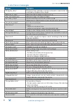
Page 29: ...cate the cause of the fault Vout applied LOCK Maintenance Fault detected when unlocking the CHAdeMO plug discon press OFF Error message End of charging display when an error occurred during charging Emergency Stop messages The Emergency Stop indicator flashes for 1 second Emergency Stop Manual Emergency Stop Emergency Stop Software Emergency Stop Emergency Stop PSU connection lost Internal Fault E...

Page 30: ..._Lock CHAdeMO plug locking coil defect BatteryIncompatib Battery voltage range not suitable for the charger BatteryMalfunction Vehicle battery fault No CAN communication at charge start up Incorrect current or voltage data Abnormal voltage at charge start up ChargingStopCtl Charge start up denied CAN or physical i o line VehicleShiftPosition Gearshift is not in neutral vehicle fault VehicleOtherFa...

Page 31: ...tected by power supervisor internal OverCurrent Output current exceeds the maximum value ERR EV Charge Status Not Ready The vehicle requests a charge but its status is not ready ERR Bad Pilot State during charge The pilot changes from status C during charging EV bad pilot state at start Pilot status is not A or B at start Error EV Not Ready The EV ready flag is not ready Error Timeout EV Session S...

Page 32: ...he charging cable and ensure that cable does not show any visual damage or deformation Conduct a visual inspection of the charging gun and ensure that gun does not show any visual damage arcing or rust Every year conduct a visual inspection of the state of the lightning protections and ensure that they are not damages I WARNING HAZARD OF ELECTRIC SHOCK EXPLOSION OR ARC FLASH To avoid danger of ele...

Page 33: ...ment End of Life Recycling This product have been optimized to reduce the amount of waste produced at the end of their useful life and for better recovery of component parts and materials when following customary processing procedures Products have been designed so that their components can be processed by conventional procedures decon tamination where this is recommended reuse and or dismantling ...

Page 34: ...www ies synergy com User Manual DIM016199 EN 34 Notes ...

Page 35: ...www ies synergy com User Manual DIM016199 EN 35 Notes ...

Page 36: ...aine Bergfeldstr 11 34130 Saint Aunès 83607 Holzkirchen France Germany Tel 33 0 4 99 13 62 80 Tel 49 0 80244633980 Fax 33 0 4 99 13 62 81 IES Synergy Inc USA IES WANMA New Energy China 330 East Maple Rd Building No 4 Wellong Technology Park Unit U No 88 Jiang Lin Rd MI43084 Troy Binjiang Hangzhou USA Zhejiang 310051 Tel 1 586 206 4410 China Tel 8657189877710 www ies synergy com DUM016199 EN_V002b ...

Reviews: