background image

Print More Materials, All For Application

— 23 —

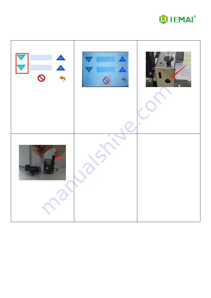
4.2.2 Unload Filament

Step 1

1. Preheat temperature is

performed

2. click the down extrusion

3.

Refer to step 10 for preheating

temperature of different

filament.

Step 2

1. After about 10cm out of the

filament

2.

Click the exit button

Step 3

1.

Waiting for the front extrusion

to withdraw from the

consumables

Step 4

1.

Press the extrusion clamp at

the far end and pull out all

consumables to complete the

unloading.

Summary of Contents for Large Scale

Page 1: ...000 Operating Instructions www iemai3d com Please read this manual carefully before starting to operate This device is a Class A product Use in a general indoor environment may cause radio interference and therefore requires the user to take appropriate protective measures ...

Page 2: ...More Materials All For Application The contents of this operating instructions may be updated periodically Scan the QR code or visit the link below to get the latest version www iemai3d com index php download ...

Page 3: ...of The Printing Platform and Auto Calibration 20 4 3 Start Printing 25 4 4 Model Removal 26 4 5 PC based WIFI LAN Control 27 5 Function Introduction 28 5 1 Power Failure Recovery 28 5 2 Filament Absent Warning 28 6 Maintenance and Care 29 6 1 Maintenance of Linear Guide and Ball Screw 29 6 2 Dust Removal from Fans 30 6 3 Nozzle Maintenance 31 6 4 Dual Print Head Nozzle Spacing Adjustment Method 33...

Page 4: ...A CF ABS PETG HIPS TPU PLA CF PLA PVA YM NT 1000 Print Head can adopt Dual Print Heads 1 75mm Filament or Single Print Head 2 85 3 0mm filament these print heads are modular and can be quickly replaced by the user In addition YM NT 1000 also adopts vacuum adsorption platform which is convenient for users to disassemble the model quickly When you use dual print heads it can support using support ma...

Page 5: ...ose the high quality filament provided by other regular filament manufacturers and users should be responsible for the loss caused by using low quality filament Please keep the consumables sealed and moisture proof if not in use for a long time please bake and dry them in advance before using them again Software Please use a 64 bit system with Windows 7 or above to run the software more than 4G of...

Page 6: ...uipment can reach 275 C its heating is strictly prohibited to touch The maximum temperature of the printing platform of this equipment can reach 120 C its heating is strictly prohibited to touch Ensure that the power supply grounding terminal is well grounded to prevent the printer from not working properly or posing a risk of electric shock Do not disassemble the case without permission be carefu...

Page 7: ...Print More Materials All For Application 4 2 Detailed Parameter 2 1 Specification ...

Page 8: ...Print More Materials All For Application 5 ...

Page 9: ...Print More Materials All For Application 6 2 2 Device Layout Front Single Door Touch screen Control Panel Main Switch SD Card Slot USB Port ...

Page 10: ...Print More Materials All For Application 7 Control Panel SD Card Slot and USB Connection Back Power Port Cooling Fan Forklift Baffle ...

Page 11: ...r Internal Filament Box Internal X Axis Negative X Axis Limit Positive X Axis Limit Z Axis Positive Y Axis Limit Y Axis Negative Y Axis Limit E1 Fixed Roller E1 Extruder E1 Filament Absent Warning E2 Fixed Roller E2 Extruder E2 Filament Absent Warning ...

Page 12: ...Print More Materials All For Application 9 Side Filament Box Electric Box ...

Page 13: ...Application 10 2 3 Interactive Interface The interactive Interface of this device adopts a 5 inch Color Touch Screen Resistive please read the following instructions carefully before first use Logic diagram of interactive interface ...

Page 14: ...original factory settings 5 Tap TPAAdjustment to correct the touch offset 6 Click WIFI to go to Figure 5 Figure 3 Info interface 1 This interface allows you to view the current coordinates of the XYZ axis 2 The current temperature of the left nozzle and right nozzle and hot bed Figure 4 About interface This interface allows you to view the name ID system version UI version and Power On Off sounds ...

Page 15: ...t information Figure 3 Manual Here can do the following 1 Select the moving unit of 0 1 10mm 2 Controls the XYZ axis for unit movement 3 Click to go back to the original point 4 Select E1 or E2 for unit extrusion Figure 4 Pre Heat interface 1 This interface allows you to set the preheat temperature of the hot bed left nozzle and Right nozzle Figure 5 Filament interface 1 Loading material 2 Unload ...

Page 16: ...fy G code file to print or delete the file Figure 3 Print Interface 1 This interface is the main interface in print You can view thumbnails 2 Hot bed Nozzle Temperature of 1 and 2 3 Elapsed time Time remaining Current speed 4 File name Print Progress Bar and more 5 You can control pause resume and stop printing 6 Press to reset during the printing process ...

Page 17: ...an Rate of Nozzle Fan E1 and Nozzle Fan E2 4 Extrusion flow 5 As well as setting power off after printing Figure 5 Emergency Stop 1 For emergencies the air switch tripped X Y Z E axis motor and hot bed high power equipment power supply shut down the machine to stop the movement you need to turn on and then turn the air switch on the electrical box to restore the power supply of high power equipmen...

Page 18: ...king photos in time 3 If serious damage please refuse to receive Step 2 1 The equipment is tightly packed and protected 2 Please be patient in removing the package 3 If you need to use tools such as knives scissors 4 Please be cautioned to avoid scratching the device Step 3 1 Check The Door Glass Whether the Control Panel is Segmentation 2 Remove the starter kit from the printer ...

Page 19: ...the XY axis to release 2 There are four paper boxes pressed under the Z axis 3 The equipment can be removed by rising the Z axis after power is applied Step 5 1 After removing all packaging 2 The equipment is shown in the picture Step 6 Toolbox Items Subject to delivery ...

Page 20: ...ning point Step 5 1 Open the cover of the installed matching power A connector do not insert your hand or other metal objects into the connector Step 6 1 The positioning point is facing the A positioning hole insert the common connector of the power cord Step 7 1 Click the main power switch Power indicator lights up Step 8 1 The screen lights up normally Then the device is successfully powered on ...

Page 21: ... whether the normal movement as shown Step 2 1 Find the positive and negative limits of XYZ axis respectively Step 3 1 Place a sheet in the Z axis negative limit slot to make the limit red light go out 2 Moving the Z axis upward and hearing a beep and no movement of the Z axis indicates that the Z positive limit switch is normal 3 Remove the sheet ...

Page 22: ...unction and temperature setting of the hot bed left nozzle and right nozzle can be done through the touch screen 2 Where the right side temperature represents the setting temperature 3 The temperature on the left side represents the actual temperature 4 First preheating recommended hot bed temperature 50 2 5 Print Head 1 and 2 210 2 6 Please be careful of high temperature and cautious operation ...

Page 23: ...onnector at the back of the machine and connect the other end to the vacuum pump Turn on the vacuum pump to make the platform plate absorb on the bottom plate Step 4 1 If the platform keeps failing to suction check whether there is debris between the platform and the bottom plate Or the surrounding baffle plate topped up the platform plate or the seal was topped up and other problems Step 5 1 Find...

Page 24: ...zzle 0 1mm away from the platform Step 9 1 Use the integrated adjustment screw and the limit height fine adjustment screw together 2 Enable the Z negative limit just trigger and start the print test Please see the detailed steps in the use of video Step 10 1 When a power failure trip occurs during use 2 Disconnect the connector of the emergency stop trigger device 3 Open the electrical box and clo...

Page 25: ...ding the filament until it cannot be fed Step 3 1 Observe that the filament reaches the front print head Step 4 1 If the material is stuck in the middle of the pipe the connector at the right side of the X axis can be taken out and fed in sections Step 5 1 After the filament is delivered to the print head 2 Preheat temperature is applied 3 Click the downward extrusion button 4 Wait for the materia...

Page 26: ...extrusion 3 Refer to step 10 for preheating temperature of different filament Step 2 1 After about 10cm out of the filament 2 Click the exit button Step 3 1 Waiting for the front extrusion to withdraw from the consumables Step 4 1 Press the extrusion clamp at the far end and pull out all consumables to complete the unloading ...

Page 27: ...ly Used Filament for Nozzle Common Engineering Plastic PLA 220 ABS 240 PETG 220 240 PVA 230 HIPS 240 PA 260 PC 260 TPU 230 Reinforced Composites PLA Composite Carbon Fiber 220 CF ABS 260 CF PLA 220 Note The temperature of the print head rises during the loading process be careful of burns ...

Page 28: ...n the IEMAI slicing softwareSave the code to the SD card Please refer to the software tutorial for detailed slicing methods Step 2 1 Insert the SD card into the card slot on the right side of the device and select the file to be printed Step 3 2 Click ready to start printing ...

Page 29: ...up the outer end of the print base plate to slowly pull out the base plate Step 3 1 Use the spatula to press firmly against the platform and gently from the corners 2 Insert the spatula into the bottom of the model and cock the spatula Step 4 1 If the model is too large to shovel down on one side 2 Start over from the other three corners until the model is shoveled down ...

Page 30: ...y the generated file to the SD card 2 and put it on the machine to print once Step 4 1 Copy the generated file to the SD card 2 and put it on the machine to print once 3 0 0 0 0 means not connected successfully Step 5 1 Enter the software and click Scan 2 Automatically reads machines in the network and connects them Step 6 1 Green status indicates successful connection Step 7 1 Preheat and movemen...

Page 31: ...of the printer has not moved after power failure otherwise it will not be able to continue printing after the last breakpoint 5 2 Filament Absent Warning Step 1 1 If the printer runs out of material during printing 2 Please select Yes in this screen to change the material Step 2 1 Unloading materials 2 Loading materials 3 E1 for the left nozzle E2 for the right nozzle 4 Unload the existing materia...

Page 32: ...ch need to be maintained and lubricated to extend the service life 1 The ball screw belongs to the high precision construction must maintain lubrication generally once a month to replace the lubricant 2 Pay attention to the cleanliness of the environment to prevent dust and impurities from entering 3 To prevent the impact of the ball screw resulting in the deformation of the screw affect the fluid...

Page 33: ...f the motherboard and prevent the drive from overheating and out of step phenomenon Step 2 Remove the dust cover Insert the four corners of the dust cover from the dust cover to gently remove the dust cover Step 3 Clear the dust on the dust cover and fan Use the air gun to remove the dust on the sponge inside the dust cover and blow the dust on the fan pay attention to the fan when blowing the pre...

Page 34: ...int item impact so need to be cleaned Step 1 Heat up the nozzle the last printing temperature shall prevail Step 2 Use tweezers to hold a soft fiber cloth or some other high temperature resistant soft goods wipe clean prohibit the use of sandpaper blades and other sharp with corrosive tools items grinding cleaning Note the nozzle high temperature operation attention to burns ...

Page 35: ...Step 3 take out the new nozzle using raw material tape clockwise around the threaded part of the nozzle about 7 turns and press out the threads Step 4 Use the pliers sleeve to re install the nozzle into the print head Note the entire operation of the nozzle has been in a high temperature state be careful of high temperature hot hands recommended to wear protective gloves Nozzle replacement require...

Page 36: ...d to move to the positive direction of the Y axis 8 Decrease the Y axis spacing negative Step 3 1 Open the slicing software 2 Adjust the parameters in the print head settings 3 Make up the difference according to the gap produced by printing 4 Difference between the right printhead and the left printhead Step 4 1 Print the two color miniature again 2 According to the printing effect to the left no...

Page 37: ...ad Disassembly and Maintenance 6 5 1 Print head disassembly method and fan cleaning Step 1 Disassembling the print head Step 2 Clean the extruded tooth surface with a brush Step 3 Simultaneous extrusion tooth cleaning at the end Step 4 Cleaning with a brush ...

Page 38: ... Take out the spring Step 6 1 Unscrew the screws as shown 2 Remove the clip Step 7 1 Remove the old extruded gear by loosening the top wire of the extruded gear Step 8 1 Move the extrusion tooth back and forth to the concave arc of the gear with the lowest point and the centerline of the feed hollow on the same vertical line and fix the extrusion tooth ...

Page 39: ...print head Step 2 Clean the extruded tooth surface with a brush Step 3 Simultaneous extrusion tooth cleaning at the end Step 4 Cleaning with a brush Step 5 If the tooth surface is severely worn replace the extruded tooth First loosen the screws as shown Take out the spring Step 6 Unscrew the screws as shown Remove the clip ...

Page 40: ...1 Move the extrusion tooth back and forth to the concave arc of the gear with the lowest point and the centerline of the feed hollow on the same vertical line and fix the extrusion tooth 6 5 3 M3 Teflon tube replacement method Step 1 Unscrew the screws as shown in the figure Step 2 Remove and replace the same length of M3 Teflon tube ...

Page 41: ...erclockwise and clean the inside of the heating block threads of residue Step 4 1 Remove the old Teflon tube and insert a new tube into the throat a Phillips screwdriver can be used to round the Teflon tube steps at the top port to facilitate feeding Step 5 1 Plug the Teflon tube to the top and then use to cut flat along the port Step 6 1 Use raw material tape to wrap the threads clockwise 4 times...

Page 42: ...3 1 Take out the new replacement parts and reassemble them Step 4 1 Thermistors are protected by M3 Teflon tubes 2 Plugged into the hole using the top wire slightly flattened Teflon tube can be 3 Too much force may damage the thermistor Step 5 1 First from the front using high temperature tape wrapped 3 turns 2 Then wrap the heating block from the side for two turns Step 6 1 Use tape to wrap the t...

Page 43: ...ature or determine if the head is clogged or needs to be reloaded with material Problem 2 One or two of the X Y Z and E axes cannot be moved and an alarm sound appears when you click to move Check if the limit switch is pressed Problem 3 Opposite direction of motion Open the firmware and change the control code 1 or 1 Problem 4 the machine movement touch sound power off and shut down and again the...

Page 44: ...djust the platform and nozzle gap when the zero point is small for details see the bottom plate leveling steps 9 10 11 12 2 the first layer of the printing speed is too fast 3 it is important to adjust the temperature of the flat hot bed and the setting parameters of the fan cooling 4 and platform coating or media related may have damage to the coating or media 3 Double headed printing does not wo...

Page 45: ...ease in the setting temperature of the printhead to increase the fluidity of the consumables 3 Printing speed is too fast Check whether the printhead is clogged 8 Features that are too small cannot be printed 1 Redesign the model with a feature width at least larger than the diameter of the nozzle 2 If the model cannot be modified it may be necessary to replace the nozzle diameter of a smaller noz...

Page 46: ... length of the pumping back and pumping back speed parameters 2 When printing the printhead moves back and forth in the process because the printhead is in a heated state the glue wire will still continue to melt out Appropriately reduce temperature of the nozzle can slow down the flow of supplies after melting 13 Weak filling 1 The possibility of changing different filling patterns to make the mo...

Page 47: ...minutes so that the water in the glue evaporated to reach the maximum paste strength 3 After using for a long time when the residual glue on the platform is too much you can take off the carbon fiber board and rinse it with clean water and re glue it Attention It is recommended to use the side skirt attachment type for printing model with carbon fiber board to avoid the model printing warpage and ...

Page 48: ...e This means that the distance between the nozzle and the platform is more appropriate and such a skirt effectively increases the contact surface between the model and the platform increasing the adhesion force Attention If the nozzle is too close to the platform there is no gap between the platform and the nozzle it will lead to nozzle extrusion without supplies so printing with a good observatio...

Reviews: