ECN-581A-QM57 Multimedia Box
Page 27
Figure 3-17: LAN Connection
Step 3:
Insert the LAN cable RJ-45 connector.
Once aligned, gently insert the LAN
cable RJ-45 connector into the on-board RJ-45 connector.
Step 0:
3.5.4 Serial Device Connection
The ECN-581A-QM57 has two female DB-9 connectors on the external peripheral
interface panel for connecting to serial devices. Follow the steps below to connect a serial
device to the ECN-581A-QM57.
Step 1:
Locate the DB-9 connector
. The location of the DB-9 connector is shown in
Figure 3-13
.
Step 2:
Insert the serial connector
.
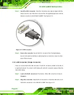
Insert the DB-9 connector of a serial device into
the DB-9 connector on the external peripheral interface. See Figure 3-18.
Summary of Contents for ECN-581A-QM57
Page 10: ...ECN 581A QM57 Multimedia Box Page 1 Chapter 1 1 Introduction ...
Page 16: ...ECN 581A QM57 Multimedia Box Page 7 Chapter 2 2 Unpacking ...
Page 20: ...ECN 581A QM57 Multimedia Box Page 11 Chapter 3 3 Installation ...
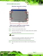
Page 22: ...ECN 581A QM57 Multimedia Box Page 13 Figure 3 1 Retention Screws Removal ...
Page 40: ...ECN 581A QM57 Multimedia Box Page 31 Chapter 4 4 BIOS ...
Page 72: ...ECN 581A QM57 Multimedia Box Page 63 Appendix A A Intel AMT Configuration ...
Page 79: ...ECN 581A QM57 Multimedia Box Page 70 Appendix B B One Key Recovery ...
Page 85: ...ECN 581A QM57 Multimedia Box Page 76 Figure B 3 Partition Creation Commands ...
Page 102: ...ECN 581A QM57 Multimedia Box Page 93 Appendix C C Safety Precautions ...
Page 106: ...ECN 581A QM57 Multimedia Box Page 97 Appendix D D Hazardous Materials Disclosure ...


