3
Status Display
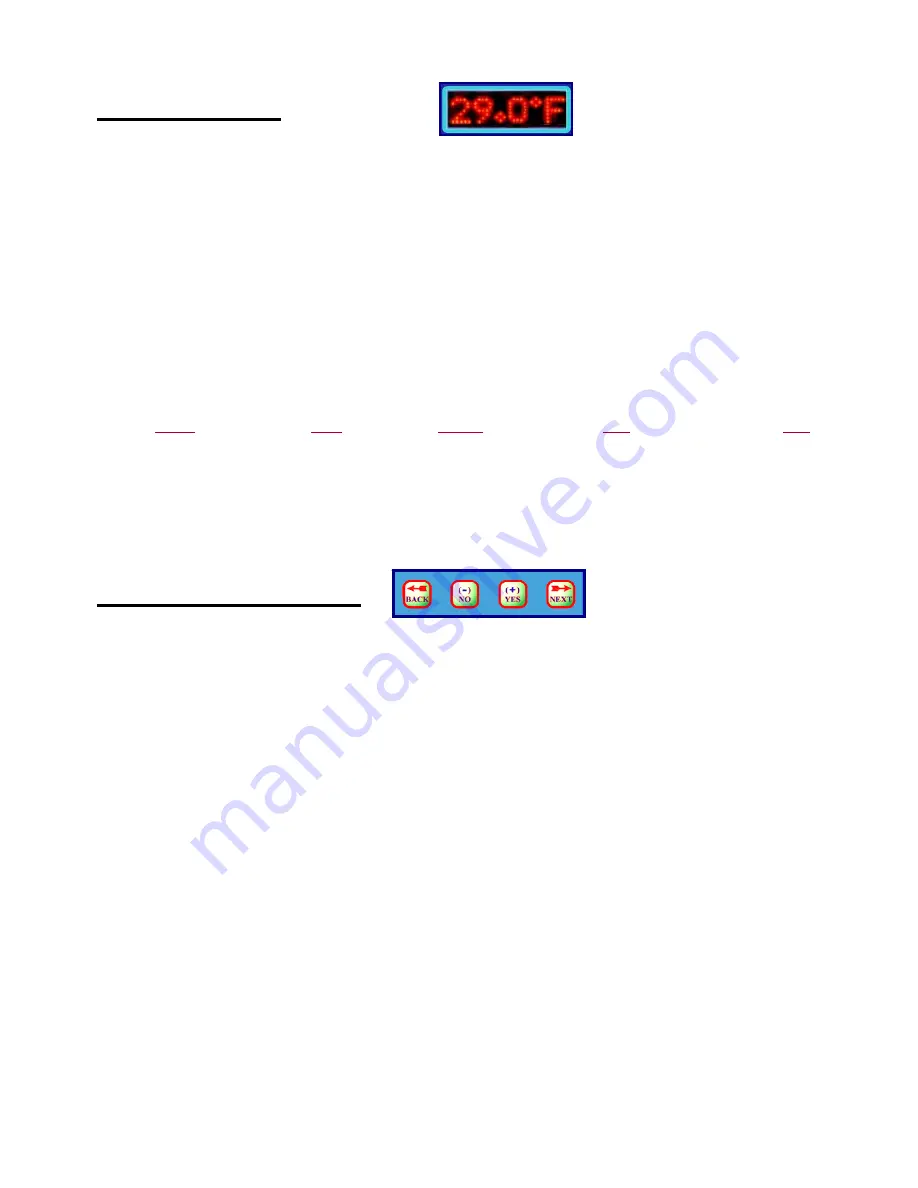
Zolar uses a bright LED dot matrix display to continuously scroll easy to read status messages. These messages include
the time of day, the temperature of all connected temperature sensors, the current ambient light intensity (if installed),
and how many days have elapsed since the last cold event and since the last power outage.
The time of day is presented in a 12-hour format, where an extra LED dot to the left of the time is illuminated to
indicate PM. If a Sensor is not physically connected, it will not be displayed. Temperatures are displayed to the nearest
0.5° Fahrenheit or nearest 0.2° Centigrade according to your Menu configuration selection. Light intensity (if used) is
expressed as a percentage of full sunlight. DAYS WARM indicates the number of days that have elapsed since the last
time a Foam Blower or Weep output was activated, while DAYS POWERED indicates the number of days since
Zolar’s power was last interrupted. Scrolling of each portion of the message is paused for 1 second while numeric
parameters are displayed to allow for easier viewing.
The following is an example status message for a configuration that includes one temperature sensor and one light
sensor. Scrolling of the display will pause for the underlined portions., parameters presented in
italic
are only displayed
if the option and/or sensor are present:
TIME: 03:27 TEMP #1:
°
F 33.5 LIGHT #2: 16.7% DAYS WARM: 164 DAYS POWERED: 973
In addition to the scrolling dot matrix display, 6 stationary LEDs to the right of the display indicate the status of all
Outputs: Weep #1, Aux #1, Weep #2, Aux #2, Auto Dialer and Foam Blower. The Weep LED is: a.) Off when it is
warm, b.) On solid when it gets cold and the relay is in the de-energized (weep water flows) portion of the weep cycle,
and c.) blinks when it gets cold and the relay is in the energized (weep water off) portion of the weep cycle. The other
LEDs are On when their corresponding outputs are On.
Configuration Menu
Just below the dot matrix LED display window is a set of four buttons (shown above) for navigating the Configuration
Menu. If the
Next
or
Back
keys are pressed, the status message is interrupted and the Configuration Menu is entered.
From the Configuration Menu, all time, temperature, or light threshold set points can be viewed by successive use of the
Next
and
Back
keys or changed by use of the
-/No
and
+/Yes
keys. If no key is pressed for 15 seconds while in the
Configuration Menu, the operator is prompted to either use the
Next
key to save the any changes made to the presently
displayed parameter and advance to the next parameter, or to use the
Back
key to cancel any changes made to this
parameter and return to the previous parameter.
PUSH NEXT TO SAVE OR BACK TO CANCEL
If, while in the Configuration Menu, no key is pressed for 30 seconds (an additional 15 seconds after the prompt to
either save or cancel), the display will revert to the status message leaving any “un-saved” parameters unchanged. Saved
parameters are stored in nonvolatile EEPROM memory where they are safe from power outages and battery failure and
will remain in effect until changed again through the Configuration Menu.
SET TIME Y/N?
After entering the Configuration Menu by pressing either the
Next
or
Back
key, the first prompt of the Configuration
Menu asks if you wish to set the time on Zolar’s Real Time Clock. If the
+/Yes
key is pressed in response to this
prompt, the current time in the Real Time Clock is displayed. If this time is not correct, the
+/Yes
and
-/No
keys can
be used to set the correct time. The time displayed will advance one minute for each press of the
+/Yes
key, or retreat
one minute for every press of the
-/No
key. If the key is held down for at least one second, the time will automatically
change at a rate of 5 minutes for every second the key his held down. Once the correct time has been reached, press the
Next
key to save this value into the Real Time Clock and proceed to the next item in Configuration Menu.


