background image

8

Installation, Support, and Maintenance Guide

iQ Satellite Router

iQ Satellite Router Front LEDs

3.1   iQ Satellite Router Front LEDs

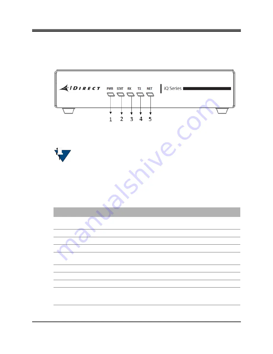
The iQ Satellite Router front panel is shown in 

Figure


3-1

.

Figure


3-1. iQ Satellite Router Front Panel LED Display

3.2   iQ Front Panel LED Status Descriptions

Descriptions for states of LEDs may vary between iDX Software Releases. Check the release 
specific 

Terminal WUI User Guide, and Release Notes 

for details. 

Figure


3-1 on page


8

 shows 

the front panel and 

Table


3-1

 describes the front panel LED color and status information:

NOTE: 

The descriptions of the LEDs may vary between iDX Software Releases. 

Check the release specific 

Terminal WUI User Guide

,

 and Release Notes 

for 

details.

Table


3-1. iQ Satellite Router Front Panel LED Descriptions


Label

Signal Color/Type Definition

POWER

Indicates iQ power status and any power-related 
problems

Off

No or low power input to the modem

 Solid Green

The modem is powered on

STATUS

Boot Sequence and Overall Hardware Status

1/2 second flashing 

Green

Remote initializing 

Solid Green 

Initialization complete

RX

Provides downstream receive status

Solid Amber

Downstream carrier configured, demodulator not yet locked

1 second flashing 

Amber

Downstream carrier configured, demodulator locked to 
downstream carrier, Network Clock Reference (NCR) not yet 
locked

Summary of Contents for iQ Desktop+

Page 1: ...Installation Support and Maintenance Guide iQ Desktop Satellite Router July 1 2019 iQ Desktop Satellite Router Installation Support and Maintenance Guide ...

Page 2: ...owner VT iDirect is a global leader in IP based satellite communications providing technology and solutions that enable our partners worldwide to optimize their networks differentiate their services and profitably expand their businesses Our product portfolio branded under the name iDirect sets standards in performance and efficiency to deliver voice video and data connectivity anywhere in the wor...

Page 3: ...top Satellite Router Revision History The following table shows all revisions for this document To determine if this is the latest revision check the TAC Web site at http tac idirect net Revision Date Updates A July 01 2019 Initial release of the document ...

Page 4: ...iv Installation Support and Maintenance Guide iQ Desktop Satellite Router Revision History ...

Page 5: ...duction 1 1 1 Features 1 1 2 Power Supply Option 2 2 Specifications 3 2 1 Mechanical and Environmental Specifications 3 2 2 Power Specifications 5 2 3 RF Specifications 5 3 Interfaces 7 3 1 iQ Desktop Satellite Router Front LEDs 8 3 2 iQ Desktop Front Panel LED Status Descriptions 8 3 3 iQ Desktop Satellite Router Rear Panel Description 10 3 4 Detecting a Tx IFL Over current Condition 10 4 Install...

Page 6: ... iQ Desktop Satellite Router 17 4 8 Using the iQ Desktop Satellite Router 17 4 9 Commissioning the iQ Desktop in DVB S2 Mode 18 5 Maintenance 19 5 1 Safety Guidelines to Observe During Servicing 19 5 1 1 Servicing 19 5 1 2 Conditions Requiring Service 19 5 2 Maintaining the iQ Desktop Satellite Router 20 5 2 1 Temperature Control 20 5 3 Troubleshooting the iQ Desktop Router 20 5 4 Repacking the iQ...

Page 7: ...n Tools 23 Figure B 1 Coax Cable Cutting Technique 26 Figure B 2 Cutting Technique for Removing Foil in the Braid 27 Figure B 3 Procedure to Cut the Quad Shield Cable 28 Figure B 4 Attaching the Compression fitting F type Connector 29 Figure B 5 Compression fitting F Type Weatherproof Plug and Tool 29 Figure B 6 RJ 45 Cable Connectors Receptacle and Plug 30 Figure B 7 Holding the RJ 45 Cable Conne...

Page 8: ...escriptions 8 Table 3 2 iQ Desktop Satellite Router Rear Panel Connector Descriptions 10 Table 3 3 iQ Desktop Front Panel LEDs During Over current 11 Table 5 1 Troubleshooting Events and Actions to Take 20 Table A 1 Recommended Installation Tools and Equipment 23 Table B 1 Coax Trim Dimensions 27 Table B 2 Ethernet Port Pinouts 30 Table C 1 iQ Desktop DC Power Module Connector Parts 33 Table C 2 P...

Page 9: ...rk Operator responsible for maintaining the iDirect Network Only qualified service personnel should install the iQ Desktop Satellite Router Familiarity with cabling and wiring practices is beneficial Manual Contents In addition to the information in this chapter this manual also includes the following Chapter 1 Introduction on page 1 provides an overview and description of the iQ Desktop Satellite...

Page 10: ...ers as well as eLearning in the installation operation maintenance and management of iDirect satellite networks For training course descriptions and available training dates visit the iDirect web site Training and Services at http www idirect net Training and Services aspx or call 1 800 648 8240 for class registration and information Getting Help The iDirect Technical Assistance Center TAC and the...

Page 11: ...s idirectgov com For sales or product purchasing information contact iDirect Corporate Sales at the following telephone number or e mail address Telephone 703 648 8000 E mail sales idirect net Warranty RoHS WEEE Declaration of Conformity Complete iDirect hardware product statements for the iQ Desktop Satellite Router are available at these Web sites http www idirect net warranty for the hardware w...

Page 12: ...xii Installation Support and Maintenance Guide iQ Desktop Satellite Router About ...

Page 13: ...ional features as network size and performance demands grow over time This chapter contains the following sections Section 1 1 Features on page 1 Section 1 2 Power Supply Option on page 2 This manual explains how to safely install and maintain the iQ Desktop Satellite Router The iQ Desktop Satellite Router is shown in Figure 1 1 Figure 1 1 iQ Desktop Satellite Router 1 1 Features Highlights Single...

Page 14: ...outer Power Supply Option 1 2 Power Supply Option The iQ Desktop Satellite Router is available with the following power supply configurations Option 1 100 240 VAC Single Phase to 24 VDC 65 W Option 2 100 240 VAC Single Phase to 24 VDC 90 W Option 3 65 W DC Power Supply ...

Page 15: ...ental specifications The mechanical and environmental specifications are listed in Table 2 1 Table 2 1 Mechanical and Environmental Specifications Category Description Dimensions W 7 2 in 18 28 cm x D 4 4 in 11 17 cm x H 1 75 in 4 44 cm Weight 0 91 lbs 0 41 kg Heat Dissipation 15W average Airflow Forced Air Cooling Venting to be unobstructed Ambient Temperature Operational Storage 65 W AC PSU 0 to...

Page 16: ...G 0 3 ms half sine 50 G 1 3 ms half sine Vibration Operational Survival Remains operational when exposed to 0 21 Grms with the following profile Survives but may not meet its operational specifications when exposed to 2 09 Grms with the following profile Table 2 1 Mechanical and Environmental Specifications continued Category Description Frequency Slope PSD 5 to 350 Hz 0 0 0001 g2 Hz 300 to 500 Hz...

Page 17: ...upply Unit Consumption Option 1 1 4 A MAX Option 2 1 2 A MAX Option 3 9 A MAX iQ Desktop DC Consumption Option 1 and 3 65 W MAX Option 2 90 W MAX DC Power Out TX Output Connector 24 VDC 2 3 A MAX over operating temperature DC Power Out RX Connector 13 18 21 VDC 500mA Max Protection Internal inside power supply Over voltage protection Over current protection Short circuit protection AC Power Cord S...

Page 18: ...rier QPSK 32APSK 125 10 log Fsym sps dBm 64APSK 256APSK 115 10 log Fsym sps dBm Tx SSB Phase Noise Transmit Carrier Suppression 35dBc max over operating temperature and frequency band Spurious Harmonic Content In band 900 2400MHz with output at 30dBm 35dBc Transmitter Muting 50 dB min between carrier on and off states within 0 1 us at the same attenuation state Modulator Spectral Shaping DVB S2 ET...

Page 19: ...uter physical interfaces and LEDs and contains the following sections Section 3 1 iQ Desktop Satellite Router Front LEDs on page 8 Section 3 2 iQ Desktop Front Panel LED Status Descriptions on page 8 Section 3 3 iQ Desktop Satellite Router Rear Panel Description on page 10 Section 3 4 Detecting a Tx IFL Over current Condition on page 10 ...

Page 20: ...s information NOTE The descriptions of the LEDs may vary between iDX Software Releases Check the release specific Terminal WUI User Guide and Release Notes for details Table 3 1 iQ Desktop Satellite Router Front Panel LED Descriptions Label Signal Color Type Definition POWER Indicates iQ Desktop power status and any power related problems Off No or low power input to the modem Solid Green The mode...

Page 21: ...ransmitter Solid Amber Transmitter is disabled 1 second flashing Amber Transmitter acquiring upstream connection Solid Green Transmitter upstream connection acquired NET Modem Network Status Indicates the state of the satellite network connection 1 second flashing Green Network acquisition in progress Solid Green Network acquired Table 3 1 iQ Desktop Satellite Router Front Panel LED Descriptions c...

Page 22: ...ort detects a over current Table 3 2 iQ Desktop Satellite Router Rear Panel Connector Descriptions Callout Label Interface Definition and Connector Type 6 TX L Band Transmit signal to Block Up Converter BUC capable of 10 MHz or 50 MHz Reference 75 Ohm F Type 7 Reset iQ Desktop internal reset button 8 RX L Band Receive signal from Low Noise Block Down Converter LNB 75 Ohm F Type 9 UART Console iQ D...

Page 23: ...us BUC Supply LNB Supply Label Signal Color Type In network Normal operation On On PWR Green Solid STAT Green Solid Rx Green Solid Tx Green Solid Net Green Solid Tx IFL Over current condition Detected will remain in this state for 5 minutes or until user intervention Off On PWR Green Solid STAT Red flash 1 sec Rx Yellow flash 1 sec Tx Yellow flash 1 sec Net Off Listening Mode waiting for user inte...

Page 24: ...12 Installation Support and Maintenance Guide iQ Desktop Satellite Router Detecting a Tx IFL Over current Condition ...

Page 25: ...ith AC Option 1 and 2 or DC Option 3 Power Supplies on page 16 Section 4 7 Configuring the iQ Desktop Satellite Router on page 17 Section 4 8 Using the iQ Desktop Satellite Router on page 17 Section 4 9 Commissioning the iQ Desktop in DVB S2 Mode on page 18 4 1 Installation Steps at a Glance The following steps must be followed for successful installation of the iQ Desktop Satellite Router Each st...

Page 26: ...h as radiators heat registers stoves or other products including amplifiers that produce heat Attachments Do not use attachments unless recommended by the manufacturer Grounding Never defeat the ground conductor or operate the equipment without a suitably installed ground conductor Contact the appropriate electrical inspection authority or an electrician if it is uncertain that suitable grounding ...

Page 27: ... Router Installation and Commissioning Guide for the release of software installed on the system and for instructions 4 2 Tools and Supplies Required for Installation Appendix A Tools Needed on page 23 specifies recommended tools and supplies used when installing the iQ Desktop Satellite Router 4 3 Unpacking iDirect Equipment The satellite router and related equipment may be shipped in one or more...

Page 28: ... Noise Block Converter 4 5 Preparing the PC for Connection to the iQ Desktop Satellite Router See Section 3 1 iQ Desktop Satellite Router Front LEDs on page 8 for more information about the LEDs as well as either the iDX Release Notes and iDX Satellite Router Installation and Commissioning Guide and Terminal WUI User Guide Confirm the PC Use Management port ETH 2 192 168 0 1 for initial configurat...

Page 29: ...er in the power supply 6 Set the iQ Desktop power module switch to the ON position 1 4 7 Configuring the iQ Desktop Satellite Router When the iQ Desktop Satellite Router is physically installed downloading the software and configuration of the satellite router need to be completed Refer to the Terminal WUI User Guide for the release of software installed on the system and for instructions To downl...

Page 30: ...minal WUI User Guide 3 Upload the option files using the Terminal WUI For information on how to upload the software see the Software and Configuration section in the Terminal WUI User Guide 4 Reboot the remote 5 Commission the remote using the Terminal WUI For information on how to commission the remote see the Commissioning a Terminal chapter in the Terminal WUI User Guide 6 Once the commissionin...

Page 31: ...llite Router internal assembly Opening and removing covers exposes dangerous voltages and or other hazards There are no user serviceable parts inside Opening the units will void the warranty Refer all servicing to qualified service personnel 5 1 2 Conditions Requiring Service Disconnect the iQ Desktop Satellite Router from the power source and refer servicing to qualified service personnel if any ...

Page 32: ...ribes the most common iQ Desktop Satellite Router troubleshooting events and actions to take Consult with the iDirect TAC when considering a reset Reset functions are described in Section D 1 Level 0 Reset on page 37 WARNING This unit is not serviceable Return unit to provider for all servicing issues ATTENTION Cette unité n est pas réparable sur site Renvoyer au fournisseur pour tout réparation T...

Page 33: ...sical damage 2 Perform a Level 1 reset Boot into Recovery mode so that the iQ Desktop Satellite Router Management port ETH 2 will have the default IP address 192 168 0 1 Load new package options configuration files with a new IP address if desired 3 Reboot with a Level 0 reset and connect with the current known IP address See Appendix D iQ Desktop Satellite Router Reset on page 37 for more informa...

Page 34: ...22 Installation Support and Maintenance Guide iQ Desktop Satellite Router Repacking the iQ Desktop Satellite Router ...

Page 35: ...ed to install related equipment and cables Test equipment may be required to check signal power levels and communication links Figure A 1 Recommended Installation Tools Table A 1 Recommended Installation Tools and Equipment Quantity Tool 1 Number 2 Phillips screwdriver 1 F type Compression Tool 1 RG 6 Coax Stripper or RG 11 as required 1 Coax Wire Cutter Length as Needed RG 6 or RG 11 solid copper...

Page 36: ...24 Installation Support and Maintenance Guide iQ Desktop Satellite Router ...

Page 37: ...ble lengths less than or equal to 260 feet 79 meters Before connecting the cables connectors on each end must be installed The center conductor must be straight and extend 1 8 inch 3 2 mm beyond the end of the F connector and the connector should be securely crimped to the cable If different types of coaxial cable are used other than the recommended quad shield RG 6 or RG 11 the following problems...

Page 38: ...urn loss of 10 dB or more To terminate the cables with F Type connectors 1 Cut off each end of the coax cable squarely using the proper cable cutter as shown in Figure B 1 Figure B 1 Coax Cable Cutting Technique NOTE Excessive DC Resistance will result in excessive voltage drop across the IFL cable Hence the voltage at the BUC may be too low to operate properly NOTE Appendix A Tools Needed on page...

Page 39: ...r such as the LC CST 1257 from Paladin Tools 3 Remove any foil in the braid as shown in Figure B 2 Figure B 2 Cutting Technique for Removing Foil in the Braid 4 Fold the braid back over the jacket and trim the braid to the length as defined under Length C in Table B 1 on page 27 and Figure B 3 Table B 1 Coax Trim Dimensions Length A inch mm Length B inch mm Length C inch mm RG 6 5 8 15 9 1 4 6 4 3...

Page 40: ... B in Table B 1 on page 27 Remove any dielectric residue 7 If the conductive foil is burred then smooth out the burr so that the edge area where the dielectric material was removed is smooth and provides a lead in for the connector mandrel 8 Install the RG 6 connector compression sleeve or mandrel top left A in Figure B 4 over foil and underneath the braid A good weatherproof outdoor connector man...

Page 41: ...tor only protrudes 1 8 inch 3 2 mm nominally beyond the rim of the F connector Trim if necessary NOTE Since the RG 11 connector has a built in center pin ensure that the coax center pin makes contact to the internal seizing pin of the connector Refer to Figure B 4 CAUTION The center conductor length must be a minimum of 1 16 inch 1 6 mm to a maximum of 1 8 inch 3 2 mm protrusion beyond the rim of ...

Page 42: ...h the iQ Desktop Satellite Router It is not necessary for the PC to auto sense Details of the iQ Desktop Satellite Router LAN Ethernet port pinouts are described in Section B 2 1 and Section B 2 2 defines straight through and crossover cables B 2 1 Ethernet Port Pinouts Table B 2 lists the pinouts for the Ethernet ports labeled ETH 1 ETH 2 of the iQ Desktop Satellite Router and the pinout order is...

Page 43: ...ure B 7 The sequence of the colored wires should be as follows Straight through The colored wires are in the same sequence at both ends of the cable Crossover The first far left colored wire at one end of the cable is the third colored wire at the other end of the cable and the second colored wire at one end of the cable is the sixth colored wire at the end of the cable Figure B 7 Holding the RJ 4...

Page 44: ...32 Installation Support and Maintenance Guide iQ Desktop Satellite Router Ethernet Port Pinouts ...

Page 45: ...nected to ve terminal in the Telecom case this would be 48V and the positive most voltage is always connected to the ve terminal in the Telecom case this would be 0VR The Chassis can be referenced to ve ve or left floating i e not connected to either ve or ve as required because the power module is fully isolated input to chassis Table C 1 iQ Desktop DC Power Module Connector Parts Name Descriptio...

Page 46: ...n Relief and Cable Tie Cable Entry Housing Strain Relief and Cable Tie included in kit P N 1803947 and cable tie Table C 1 iQ Desktop DC Power Module Connector Parts Name Description Diagram or Reference Table C 2 Power Module Power Cable Installation Instructions Detail Step Instructions Diagram 1 Strip approximately 1 4 inch of insulation from the ends of three appropriately sized 14 18 AWG DC i...

Page 47: ... of the holes in the right half of the strain relief clip 4 1 Wrap the cable tie around the wires and tighten 2 Insert the three screw end of the terminal block plug into the half of the strain relief clip Be sure the two end screw holes fit securely into the two small protruding screw holders 5 Clip the other half of the strain relief clip around the cable entry housing and tighten the cable tie ...

Page 48: ... Evolution X1 Satellite Router 6 Insert the finished terminal block plug with the cable entry housing into the terminal block header in the power supply Table C 2 Power Module Power Cable Installation Instructions Detail Step Instructions Diagram ...

Page 49: ...ot Terminal Used to boot to a newly loaded software image and configuration Recovery initiate a Level 0 reset D 2 Level 1 Reset Level 1 reset provides a means of returning the router to factory default settings Level 1 reset features Initiated by Pressing the reset button and keeping it pressed for more than 10 seconds see Section 3 3 iQ Desktop Satellite Router Rear Panel Description on page 10 f...

Page 50: ...covery of modem only and new options file configuration and software must be loaded Router boots with factory default image default options file software and passwords access to Terminal WUI is available at the Management port ETH 2 at 192 168 0 1 Recovery none reload software options file configuration ...

Page 51: ......

Page 52: ...iDirect 13861 Sunrise Valley Drive Suite 300 Herndon VA 20171 6126 1 703 648 8000 1 866 345 0983 www idirect net Advancing a Connected World ...

Reviews: