0901082 Rev: D (08/08)
Page 6 of 12
PROBE INSTALLATION (if required)
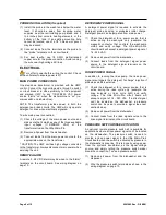
(1) Install the probe in the wash tank below the water
level. It should be away from incoming water
supplies, near the recirculating pump intake, and 3
to 4 inches from corners, heating elements, or the
bottom of the tank. If an existing mounting hole
cannot be located, use of a 7/8" hole saw or punch
may be desired.
(2) Connect leads from the terminals on the probe to
the “probe” terminals on the circuit board.
(3) For best results, use 18 AWG multi-stranded
copper wire for the probe connection. Avoid running
the wire near high voltage AC lines.
ELECTRICAL
Turn off all power before wiring the control. Check
with a voltmeter to ensure power is off.
MAIN POWER CONNECTION
One step-down transformer is provided with the UMP
control. Connect the high voltage side, through a switch
or circuit breaker in close proximity to the equipment
and marked UMP, to any 115/208/230 VAC power
source that is “on” when the dishmachine is “on” (i.e.
mains switch on dishmachine).
NOTE: The transformer provides power to both the
detergent and rinse circuits. The UMP will only operate
detergent or rinse when electrically signaled.
To wire main power connection:
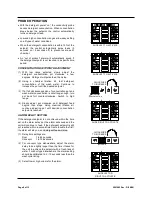
(1) Check the voltage of the main power source and
make sure that it matches one of the three available
input
voltages
(115/208/230
VAC)
of
the
transformer inside the Ultra Micro-Pro.
(2) Remove all power from the dishwasher.
(3) Connect leads from the main power source to the
appropriate wires on the transformer.
* CAUTION: The UMP unit has high voltage connected
to the transformer. Always disconnect main power when
servicing the unit.
REMOTE ALARM
A remote 3 - 28 VDC alarm may be wired to the “alarm”
terminals on the circuit board. See wiring diagram on
page 10.
DETERGENT POWER SIGNAL
A detergent power signal is required to activate the
detergent probe sensing or probeless initial charge.
Detergent power can be jumpered from main power.
(1) Check the dishwasher for a power source that is
active during the washcycle only (example: the
magnetic contactor that controls the washpump
motor) and verify voltage. The Ultra Micro-Pro
circuit board will accept a detergent power signal of
14 - 240 VAC.
(2) Remove all power from the dishwasher.
(3) Connect leads from the detergent signal power
source to the detergent signal terminals on the
circuit board.
RINSE POWER SIGNAL
In addition to running the rinse pump, the rinse power
signal also triggers the detergent “recharge” injection if
probeless mode is selected
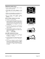
(1) Check the dishwasher for a power source that is
active during the rinse cycle only (example: the
rinse solenoid or rinse cycle light) and verify
voltage. The Ultra Micro-Pro circuit board will
accept a signal of 14 - 240 VAC. If a direct signal
can’t be located on the dishwasher, a pressure
switch can be used to provide a signal (see next
section below).
(2) Remove all power from the dishwasher.
(3) Connect leads from the rinse signal source to the
rinse signal terminals on the circuit board.
PRESSURE SWITCH RINSE ACTIVATION
An optional remote pressure switch kit is available for
applications where a rinse power signal can’t be located
on the dishwasher. The pressure switch is used to
provide a rinse power signal to the Ultra Micro-Pro’s
circuit board when the switch is activated by pressure in
the dishwasher’s rinse line. This is done by using power
from the system’s transformer as the signal voltage
source
, and simply letting the pressure switch make/
break the connection. To use a pressure switch:
(1) Remove all power from the dishwasher and the
dispenser.
(2) Wire the pressure switch terminals as shown in the
wiring diagram on page 10.

