background image

System Manual HS3A-H21M4


18 

GND

24 V DC

IB

1

U

B

2

O

A

3

O

B

4

M12 plug-connector

(8-pin)

O

U

T

5

IA

6

0

V

7

R

S

T

8

-K1

-K2

-M1

M

+

-

+

-

GND

24 V DC

HS3A #1

IB

1

U

B

2

O

A

3

O

B

4

M12 plug-connector

(8-pin)

O

U

T

5

IA

6

0

V

7

R

S

T

8

-K1

-K2

-M1

-M2

M

M

+

+

-

Connection of a single HS3A 

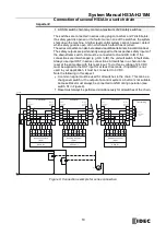
If a single HS3A is used, connect the device as shown in Figure 7. The OUT output 
can be connected routed to a control system as a monitoring output. 

The switch can be reset via the RST input. To do this, a voltage of 24 V DC is 
applied to the RST input for at least 3 seconds. The RST input must be con-
nected to 0 V DC if it is not used. 

Important! 

The subsystem HS3A complies with PL e in accordance with EN ISO13849-1. To 
integrate the subsystem in a category 3 or 4 structure, it is necessary to monitor 
the downstream load (the feedback loop must be monitored). 
These examples show only an excerpt that is relevant for connection of the HS3A 
system. The example illustrated here does not show complete system planning. 
The user is responsible for safe integration in the overall system. 


Figure 7: Connection example for a single HS3A 

Warning! 

In case of an error, loss of the safety function through incorrect connection. 

  To ensure safety, both safety outputs (OA and OB) must always be evalu-

ated. Single-channel use of the safety outputs leads to a loss of the cate-
gory in accordance with EN ISO 13849-1. 


Figure 8: Example of incorrect connection 

HS3A #1 

Summary of Contents for HS3A Series

Page 1: ...110407 04 05 15 B 1221 3 System Manual Non Contact Safety Switch HS3A H21M4 Multicode Original ...

Page 2: ...ection for power supply 13 Requirements for connection cables 14 Maximum cable lengths 15 Pin assignment of HS3A 17 Connection of a single HS3A 18 Connection of several HS3A in a switch chain 19 Notes for operation with safe control systems 20 Setup 21 LED displays 21 Functional check 22 System status table 23 Technical data 24 Technical data for HS3A 24 Technical data for actuator HS9Z ZH31 27 Or...

Page 3: ...arts of control systems Part 1 General principles for design EN ISO 12100 Safety of machinery General principles for design Risk assessment and risk reduction IEC 62061 Safety of machinery Functional safety of safety related electrical electronic and programmable electronic control systems Correct use includes observing the relevant requirements for installation and operation particularly based on...

Page 4: ...is purpose the overall system must be validated e g in accordance with EN ISO 13849 2 Correct use requires observing the permissible operating parameters see Technical data on page 24 If a product data sheet is included with the product the information on the data sheet applies in case of discrepancies with the operating instruc tions ...

Page 5: ...se after every fault Independent of these checks the safe function of the safety guard should be checked at suitable intervals as part of the maintenance schedule Warning Danger to life due to improper installation or due to bypassing tampering Safety components fulfill a personal protection function Safety components must not be bypassed turned away removed or oth erwise rendered ineffective On t...

Page 6: ...operating instructions and the system man uals are always available during mounting setup and servicing IDEC cannot provide any warranty in relation to the readability of the CD ROM supplied for the storage period required For this reason you should archive a printed copy of the system manual You can download these documents from http www idec com ...

Page 7: ... multicode devices a specific code is not polled but instead it is only checked whether the actuator is of a type that can be detected by the system multicode detection There is no exact comparison of the actuator code with the taught in code in the safety switch unique code detection The system possesses a low coding level When the safety guard is closed the actuator is moved towards the safety s...

Page 8: ...on The detailed switching states for your switch can be found in the system All safety outputs monitoring outputs and ind cating LEDs are described there Safety guard closed actuator n operating distance and permissible coding detected Manua h t itch ca b u m n r actu r System Manual HS3A c e o af p n o t off off H21M4 The detailed switching states for your switch can be found in the system All sa...

Page 9: ...rections It is marked by the red face 1 Remove the top part of the mounting base and push the bottom part off the mounting base off the HS3A 2 Unscrew the screws on the fastening bracket 3 Undo the read head from the fastening bracket and tilt HS3A forward by 90 The active face is now pointing downward 4 Hold the fastening bracket tight and turn HS3A by 180 5 Re tighten the screws for the read hea...

Page 10: ...5 2 and 5 3 for information about fastening the safety switches and the actuator Important From the assured switch off distance Sar the safety outputs are safely shut down Refer to page 28 When mounting several HS3A observe the stipulated minimum distance to avoid mutual interference If the actuator is installed flush the switching distance changes as a function of the installation depth and the s...

Page 11: ...e side lobes a minimum distance is to be maintained in case of a side approach direction See section Typical operating distance when the safety guard is open up to the distance Sar assured switch off distance a hazard is excluded Refer to page 28 the actuator is positively mounted on the safety guard e g by using the safety screws included they cannot be removed or tampered with using simple means...

Page 12: ...S3A deliver a level of 24 V DC in the switched on state All the electrical connections must either be isolated from the mains supply by a safety transformer according IEC 61558 2 6 with limited output voltage in the event of a fault or by other equivalent isolation measures PELV All electrical outputs must have an adequate protective circuit for inductive loads The outputs must be protected with a...

Page 13: ... approval The devices are tested according to the requirements of UL508 and CSA C22 2 No 14 protection against electric shock and fire Safety in case of faults The operating voltage UB is reverse polarity protected The safety outputs are short circuit proof A short circuit between the safety outputs is detected by the switch A short circuit in the cable can be excluded by laying the cable with pro...

Page 14: ...usage of other connection components the requirements in the fol lowing table apply IDEC provides no warranty for safe function in case of failure to comply with these requirements Observe the following requirements for the connection cables Parameter Value Unit Conductor cross section min 0 34 mm 2 R max 60 Ω km C max 120 nF km L max 0 65 mH km Recommend cable type LIYY 8x or 5x for series connec...

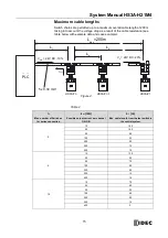
Page 15: ... a result of the cable resistance see table below with example data and case example n Iout mA L1 m Max number of Switches for series connection Possible output current per channel OA OB Max cable length from the last switch to the control system 5 10 150 25 100 50 80 100 50 200 25 300 15 400 10 6 10 120 25 90 50 70 100 50 200 25 300 15 400 10 10 10 70 25 60 50 50 100 40 200 25 300 15 400 5 Vmin 2...

Page 16: ...values can now be determined using the example table 1 Select the corresponding section in the column n max number of switches Here 6 switches 2 In column IOUT possible output current per channel OA OB find a current greater than or equal to 75 mA Here 100 mA It is then possible to determine the maximum cable length from the last HS3A switch 6 to the control system from column L1 Here a length of ...

Page 17: ...tion side of HS3A Figure 6 Pin assignment of HS3A Pin Designation Description Wire color 1 IB Enable input for channel 2 White 2 UB Power supply 24V DC Brown 3 OA Safety output channel 1 Green 4 OB Safety output channel 2 Yellow 5 OUT Monitoring output Gray 6 IA Enable input for channel 1 Pink 7 0V Ground 0V DC Blue 8 RST Reset input Red ...

Page 18: ...The subsystem HS3A complies with PL e in accordance with EN ISO13849 1 To integrate the subsystem in a category 3 or 4 structure it is necessary to monitor the downstream load the feedback loop must be monitored These examples show only an excerpt that is relevant for connection of the HS3A system The example illustrated here does not show complete system planning The user is responsible for safe ...

Page 19: ...4 V DC must be applied to the RST input for at least 3 seconds If input RST is not used in your application it must be connected to 0 V DC Note the following in this aspect A common signal must be used for all switches in the chain This can be a changeover switch or the output of a control system A button is not suitable because Reset must always be connected to GND during operation see switch S1 ...

Page 20: ... current Always connect inputs IA and IB directly to a power supply unit or to outputs OA and OB of another HS3A device series connection Pulsed signals must not be present at inputs IA and IB The safety outputs OA and OB can be connected to the safe inputs of a control system Prerequisite The input must be suitable for pulsed safety signals OSSD signals e g from light curtains The control system ...

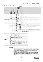
Page 21: ...gnificance STATE Green illuminated Normal operation flashing Teach in operation or power Up Actuator in limit range refer to System status table on page 23 for further signal functions DIA Red illuminated Internal electronics fault Fault at the inputs outputs Table 3 ...

Page 22: ... 1 Switch on operating voltage The machine must not start automatically HS3A H21U4 carries out a self test The green STATE LED flashes for 10 s with 10 Hz The green STATE LED then flashes at regular intervals 2 Close all safety guards The machine must not start automatically The green STATE LED illuminates continuously 3 Enable operation in the control system 4 Open the safety guard The machine mu...

Page 23: ... code not readable X off 4 Output fault e g short circuits loss of switching ability X off 5 Internal fault e g component faulty data fault or short circuits of outputs X off X X Internal fault with door fault Key to symbols LED is not illuminated LED is illuminated 10Hz 8s LED flashes for 10s at 10Hz 2Hz LED flashes at 2Hz n LED flashes n times and this is then repeated 1 inverse LED flashes illu...

Page 24: ...OB LOW U OA U OB 0 1 Switching current per safety output 1 400 mA Utilization category acc to EN IEC 60947 5 2 DC 13 24 V 400mA Caution outputs must be protected with a free wheeling diode in case of inductive loads Off state current Ir 0 25 mA Monitoring output OUT 1 p switching short circuit proof Output voltage 0 8 UB UB V DC Max load 200 mA Rated insulation voltage Ui 300 2 V Rated impulse wit...

Page 25: ...a certain time the safety outputs OA and OB will be switched off The device switches to fault state Risk time according to EN 60947 5 3 If an actuator moves outside the op erating distance the safety outputs OA and OB are deactivated at the latest after the discrepancy time Discrepancy time The safety outputs OA and OB switch with a slight time offset They assume the same signal state at the lates...

Page 26: ...4 OB 5 OUT 6 IA 7 0V 8 RST Dimension drawings and connector assignments Connector assignment for HS3A H21M4 8 pin plug and Y distributor 8 pin socket Sensor head HS3A H21M4 Terminating plug HS9Z H3TP 4 pin plug Y distributor HS9Z H3YD Figure 10 Mounting screws are not supplied with the sensor head and must be provided by the user Use stainless steel or non metallic screws 1 N m M5 ...

Page 27: ...Tightening torque 1 N m Note When tightening safety screws it will be impossible to remove them Parameter Value Unit min typ max Housing material PBT Dimensions 40 40 10 mm Weight 0 025 kg Ambient temperature 25 70 Degree of protection acc To EN IEC 60529 IP 67 IP 69K Installation position Active face opposite read head Power supply Inductive via read head Figure 13 ...

Page 28: ...eases to 30mm Typical operating distance Only in conjunction with actuator HS9Z ZH31 on surface mounting Figure 14 Typical operating distance Parameter Value Unit min typ max Switch on distance 15 1 mm Assured switch on distance Sao 13 Switching hysterisis 1 5 2 5 Assured switch off distance Sar 58 For a side approach direction for the actuator and safety switch a minimum distance of s 6mm must be...

Page 29: ...he related component must be replaced completely The replacement of individual parts in a safety component is not permitted Regular inspection of the following is necessary to ensure trouble free long term operation Check the switching function see section Functional check on page 22 Check the secure fastening of the devices and the connections Check for soiling No servicing is required repairs to...

Page 30: ... conformity with the relevant EU harmonization legislation 2006 42 EC Machinery Directive 2014 53 EU Radio Equipment Directive 2011 65 EU Restriction of the use of certain hazardous substances RoHS Directive The safety objectives of the Low voltage Directive 2014 35 EU and EMC Directive 2014 30 EU comply with article 3 1 of the Radio Equipment Directive Applied Union harmonized legislation and ref...

Reviews: