System Manual HS3A-H21M4
25
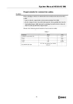
Typical system times
Please refer to the technical data for exact values.
Ready delay: After switching on, the unit carries out a self-test. The system is
ready for operation only after this time.
Switch-on time of safety outputs: The max. reaction time t
on
is the time from
the moment when the actuator is in the operating distance (safety guard
closed) to the moment when the safety outputs switch on.
Simultaneity monitoring, safety inputs (Enable inputs IA/IB): If the safety
inputs have different switching states over a certain time, the safety outputs
(OA and OB) will be switched off. The device switches to fault state.
Risk time according to EN 60947-5-3: If an actuator moves outside the op-
erating distance, the safety outputs (OA and OB) are deactivated at the latest
after the discrepancy time.
Discrepancy time: The safety outputs (OA and OB) switch with a slight time
offset. They assume the same signal state at the latest after the discrepancy
time.
Test-pulse duration at the safety outputs: The device generates its own
test pulses on the output lines OA/OB. A downstream control system must
tolerate these test pulses.
This can usually be set up in the control systems by parameter assignment.
The pulses are also output when the safety outputs are switched off.


