background image

Concord ESi - 

Installation and Servicing

39

NOTES

Summary of Contents for Concord ESi 140

Page 1: ...Your Ideal installation and servicing guide Concord ESi 140 380 3000145 2 001 A ...

Page 2: ... Burner pressure 2nd stage mbar 8 8 11 8 1st stage mbar 1st stage pressure 0 5 x adjusted 2nd stage pressure Approx flue gas volume m3 sec 0 115 0 123 0 148 0 163 0 171 0 209 0 228 0 247 0 304 Flue Gas Temperature ºC 125 133 123 125 130 126 133 140 126 CO2 6 4 7 6 3 6 4 6 8 6 5 7 7 5 6 5 Table 1 Performance Data Boiler ESi 140 ESi 160 ESi 180 ESi 200 ESi 220 ESi 260 ESi 300 ESi 340 ESi 380 Main bu...

Page 3: ...Compatibility Directive Relevant standards EN 50 081 1 EN 50 082 1 EN 55 014 The boilers are of the B11 type Gas Safety Installation and Use Regulations or rules in force It is the law that all gas appliances are installed and serviced by a CORGI registered installer in accordance with the above regulations Failure to install appliances correctly could lead to prosecution It is in your own interes...

Page 4: ...for Combined indirect pumped domestic hot water and central heating systems Independent indirect pumped domestic hot water or central heating systems Fully pumped systems may be open vented or sealed The range of boilers is NOT suitable for 1 Gravity DHW systems 2 Gravity heating systems 3 Direct domestic hot water supply WATER CIRCULATION SYSTEM Due to the compact nature of the boiler the heat st...

Page 5: ...s NOT permissible to design the system to run the boiler constantly at 40ºC flow The return temperature must not be less than 35ºC Boiler Size ESi 140 ESi 160 ESi 180 ESi 200 ESi 220 ESi 260 ESi 300 ESi 340 ESi 380 No of sections 8 9 10 11 12 14 16 18 20 Dimension A 1362 1362 1362 1362 1362 1412 1412 1412 1462 Dimension B 970 1058 1146 1234 1322 1498 1674 1850 2026 Dimension øC 250 250 300 300 300...

Page 6: ...is positioned in the flow to the system 4 The boiler is at the highest point of circulation in the system Systems designed to rise above the boiler flow tappings will automatically require a minimum static head higher than that shown 5 The position of the open vent safety pipe above the expansion cistern water level is given as a guide only The final position will depend upon the particular charac...

Page 7: ... Health and Safety Executive The information and guidance given below is not intended to override any requirements of either of the above publications or the requirements of the local authority gas or water undertakings In general commercial closed pressurised systems are provided with either manual or automatic water make up On both instances it will be necessary to fit automatic controls intende...

Page 8: ...s recommended that all chimneys are insulated and lined In the case of brick or similar structures a stainless steel rigid or flexible flue liner grade 304 316 may be used in conjunction with a 50 mm minimum thick layer of vemiculite or perlite granules between the liner and the inner skin of the chimney body Liners should be sealed at both top and bottom As the Concord ESi range of boilers is sup...

Page 9: ...e operating cycle in Frame 6 3 Multiblock gas valve comprising a safety valve and a main 2 stage valve with a filter and a minimum pressure sensitive switch 4 Ignition valve 5 Ignition burner it is used to ignite the main burner An ignition electrode and an ionisation probe are fitted to the ignition burner 6 Ignition burner sighthole 7 Ignition burner ionisation probe checks whether the flame of ...

Page 10: ...eration the safety control box automatically repeats the start up sequence If the flame is not re established then the control box will lockout RESETTING If at lockout the safety control box is reset by pressing the reset button If the first resetting does not give the expected result wait for at least 15 seconds before resetting once again Note 1 When it is started up for the first time the safet...

Page 11: ...the hire of the same if required if a 500mm b 1600mm if a 1600mm b 500mm Multiple Boiler Installations A clearance of 200mm must be allowed between boilers when installed in multiple No of boiler sections 8 9 10 11 A mm 970 1058 1146 1234 No of boiler sections 12 14 16 18 A mm 1322 1498 1674 1850 No of boiler sections 20 A mm 2026 Note Please note that boilers installed in or close to rooms in whi...

Page 12: ...40 ESi380 GK 100 Boiler body GK 101 GK 102 GK 103 GK 104 GK 105 GK 106 GK 107 GK 108 Gas train package piping base frame combustion chamber Left hand side sect 8358 0003 Intermediate sect 8358 0001 Right hand side sect 8358 0002 Set of two tie rods Package of unassemb led body accessories Draught diverter package Casing insulation package Control panel BOILER WITH UNASSEMBLED BODY 1 6 1 1 7 1 1 8 ...

Page 13: ...cks 5 on the front side Remove the flow and return pipes 6 10 COMBUSTION CHAMBER REMOVAL Before mounting the sections on the base frame remove the burner drawer 3 unscrewing the 4 M8 hex flanged nuts 4 on either side of the burner remove the tray 5 located under the burner drawer remove the combustion chamber 6 fastened by the M8 x 16 screws 7 and serrated washers located in the front and rear of ...

Page 14: ...base frame on the left or right hand side using 2 H M6x25 screws The side is to be determined according to the space available in the boiler room see Frame 7 and the mounting direction chosen Put the first section 3 in place and fasten it to the brackets 2 with 2 H8 x 30 screws H8 nuts M8N washers washers on the cast iron side Coat the edges of the side section or the sealing grooves with iron put...

Page 15: ... piece of wood Carefully apply filler on the sealing grooves 5 with a spatula so as to ensure correct tightness of the boiler body Assemble other sections using the same principle Put the assembly tool in place not supplied with the boiler Tighten gradually so as to bring about simultaneous and identical closing of both upper and lower connections Assemble the remaining sections as per the instruc...

Page 16: ...l for each pipe or flange All hydraulic connections must be carried out on the same side either on the right hand side or on the left hand side but never diagonally The pocket must in all cases be placed on the left hand side of the boiler If the flow and the return are on the left hand side put the pocket in the flow pipe opening and the 1 2 plug in the threaded flange If the flow and return are ...

Page 17: ... chamber taking care to have it resting on the lower edge of the combustion chamber walls Put the burner drawer 4 back in place and fasten it onto the combustion chamber using the 4 H M8 flanged nuts 19 HYDRAULIC TEST Screw the plugs into the pipes 1 Screw a R2 to Rp 1 2 reduction into the heating return 2 Connect the test pump to this reduction 3 Run the test for 10 minutes The test pressure must...

Page 18: ...e Apply a silicone bead 2 as shown on the picture only on the front side of the boiler Remove the nuts pre mounted on the draught diverter and fit the draught diverter stiffener 3 The nuts will be finally tightened after Frame 33 after mounting and adjusting the side panels Put the draught diverter 4 in place and fasten it onto the body using 4 H8 x 30 screws 4 DE8 serrated washers 4 nuts 4 M8N wa...

Page 19: ...nted self tapping screws Fasten the front support using 2 M8 x 25 screws 2 nuts 4 large diameter washers Put the 3 cable ties 4 in place on the control panel support Stick the data plate 5 on the front support Insert the rear insulation panel between the boiler body and the draught diverter Insert the bottom of the panel into the retaining slot Note Black insulation fabric on the outside con9049 I...

Page 20: ... insert the top under flow pipe 2 Put the right hand side insulation panel 3 in place inserting the bottom into the base frame 26 INSULATION FASTENINGS CON5273 Put the lower front insulation panel on the combustion chamber square 6 and insert it under the insulation holding square 7 Fasten the panel with clamps 8 then with strap 9 2 con9050 3 1 INSTALLATION ...

Page 21: ...Put the upper front insulation panel in place inserting it between the draught diverter and the front support Fasten it with clamps 27 UPPER FRONT INSULATION CON5274 28 TOP INSULATION CON5275 Put the top insulation panel on the draught diverter INSTALLATION ...

Page 22: ...ew 3 serrated washer and on the stiffener 4 with 1 self tapping screw 5 Put the first bracket 1 in place on the first locating stud on the front support Fix the bracket with a screw 2 Put the second bracket 3 in place on the other locating stud on the front support Fix the bracket with a screw 2 Fasten both brackets on the front panel support with two screws 4 Push the front in fill panel into pla...

Page 23: ...rs 7 6 9 10 8 5 7 con9053 32 FITTING THE SENSORS Unreel the flexible ionisation probe cable 5 and push through opening 6 located in the lower part of the control panel Refer to Frame 34 for fitting sensor to ionisation electrode Push the capillaries 7 of the thermostats the thermometer and the sensors through opening 8 Caution The non insulated parts of the capillaries must be located outside of t...

Page 24: ...ectrode electrode on the right hand side as well as the earthing wire 6 Note Take care to separate as well as possible the ionisation cable from the electrical harness of the gas train 6 5 7 CON5282 Plug the ignition circuit connector 7 plug 1 into the left hand socket below the control panel Plug gas pressure switch connector plug 2 and gas valves plug 3 into sockets as shown below the control pa...

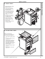
Page 25: ...l in place by locating it in the 2 notches and secure it with four self tapping screws Fit the rear deflector with three self tapping screws 36 TOP AND FRONT PANELS Note If external electrical connections are being made now these panels may be fitted later Put the lower front panel in place 1 Put the burner cables in place in the cable way 2 Fold the lug over 3 Place the rest of the cables between...

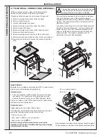
Page 26: ...ecuring screws from top of the control panel 9 Remove the securing screws from front of the control panel 10 Lower the control panel to access the connection terminal strip con9056 con9057 CABLEROUTING Separate the low voltage sensor wires from 230 V power wires in order to prevent electromagnetic interference Inside the boiler 1 Feed the connection cables through the holes in the upper rear panel...

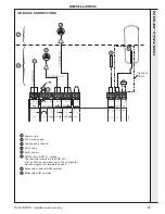
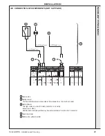
Page 27: ...nk 2 230 V main supply 3 Heating pump Circuit A 4 DHW pump 5 Boiler sensor 6 DHW sensor AD212 optional The connector supplied in the AD212 kit with the 22kOhm resistance and a 100nF capacitor must be plugged into terminals 20 and 21 7 Boiler with or without DHW calorifier 8 Boiler with DHW calorifier INSTALLATION ...

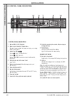
Page 28: ... CONTROL PANEL DESCRIPTION con9060 10 Switch for selecting the number of burner stages 2 stage boilers 11 Digital display Light 8 lit Boiler temperature display Light 13 lit Domestic hot water display DOMESTICHOTWATER 12 Electronic thermostat Adjustment of the average DHW storage temperature 13 Light on Indicates the display above it is showing the DHW temperature When the system is switched on it...

Page 29: ...troller contact is connected to the terminals CS on the VA CS connector Alarm indicator This light comes on when the safety control box is in safety lockout out of order Remote alarm to indicate overheat may be wired to terminals VA on the VA CS connector Room thermostat Boiler with or without calorifier 1 2 3 4 5 con9073 INSTALLATION ...

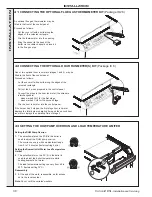
Page 30: ...wires are interchangeable wires marked CH1 for the first stage wires marked CH2 for the second stage Clip the hour run meter into the control panel If the burner has 2 stages the first stage hour run meter displays the total burner operating time and the second hour run meter displays the operating time of stage 2 con9062 43 SETTING THE DHW PUMP OVERRUN AND LOAD TEMPERATURE LIMITER con9063 1 2 Set...

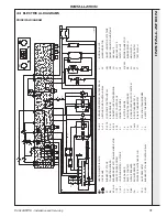
Page 31: ... J2 5 J3 4 h CH1 h CH2 TCH 1 2 A HEATING PUMP CIRCUIT A LOAD PUMP BURNER 1ST STAGE CONNECTING BOARD BURNER RESET BUTTON ALARM INDICATOR LEAK PROOFING SYSTEM HOUR RUN METER 1 2 STAGE FLUE DAMPER SAFETY CONTACT CIRCUIT BREAKER EMI SUPPRESSOR PRINTED CIRCUIT BOARD PLUG GAS PRESSOSTAT BURNER 1ST STAGE CONTROL RELAY IGNITION VALVE ALARM INDICATOR ON OFF INDICATOR 1ST STAGE ON OFF INDICATOR 2ND STAGE GA...

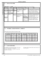
Page 32: ... Probable Cause The corresponding sensor circuit is interrupted or is short circuited If the power supply is interrupted with an alarm and no corrective action is taken then when the power is resumed the boiler will restart but continue to operate in a CH mode only and alarm will NOT be displayed The calorifier is empty or incorrectly fitted AD212 kit connector The DHW may be reactivated for 24 ho...

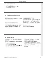
Page 33: ...gas supply cock at the meter Wait for 1 minute for temperature stabilisation then observe the pressure gauge over a period of 2 minutes Any leaks must be cured Replace all pressure test point screws Before turning the boiler on make sure that the installation is filled with water Carry out the start up operations in the order indicated below Refer to Frame 39 for identification Open the main gas s...

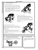
Page 34: ...essure as follows Adjust the 1st stage flow with the help of ring E Clockwise rotation decreases the pressure Counter clockwise rotation increases the pressure Tighten locking screw C 3 Adjusting the starting rate or initial flow Start rate is factory set to the minimum 9 mb starting pressure Depending on the installation conditions one may adjust the start rate setting in order to ensure an optim...

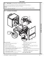
Page 35: ...Isolate the gas supply Remove the lower boiler panel 1 Remove the intermediate boiler panel 2 Disconnect gas valve connector 3 and gas pressure switch connector 4 located under the control panel Disconnect ignition transformer circuit 5 Disconnect ionisation cable 6 as well as the earthing wire on the ionisation probe side Unscrew the pipe union 7 on the gas inlet pipe Unscrew the 4 burner drawer ...

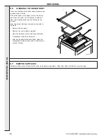
Page 36: ...and soot falling on the burners Once the burner has been removed as directed in Frame 55 Remove the top panel Remove the top insulation material Open the cleanout cover of the draught diverter If necessary clean the boiler body After having cleaned the boiler body clean the combustion chamber plate with a hand brush or vacuum cleaner CON5301 57 PAINTED SURFACES Painted surfaces may be cleaned with...

Page 37: ...Concord ESi Installation and Servicing 37 NOTES ...

Page 38: ...38 Concord ESi Installation and Servicing NOTES ...

Page 39: ...Concord ESi Installation and Servicing 39 NOTES ...

Page 40: ...nuing improvement in the design and performance of its products The right is therefore reserved to vary specification without notice The Ideal Boilers Technical Training Centre offers a series of first class training courses for domestic commercial and industrial heating installers engineers and system specifiers For details of courses please ring 01482 498 432 Ideal Installer Technical Helpline 0...

Reviews: