ID Lock 202 Multi
Installation manual
V1.1
6
Mounting the backplate and inside unit
Inside backplate
1.
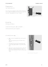
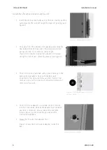
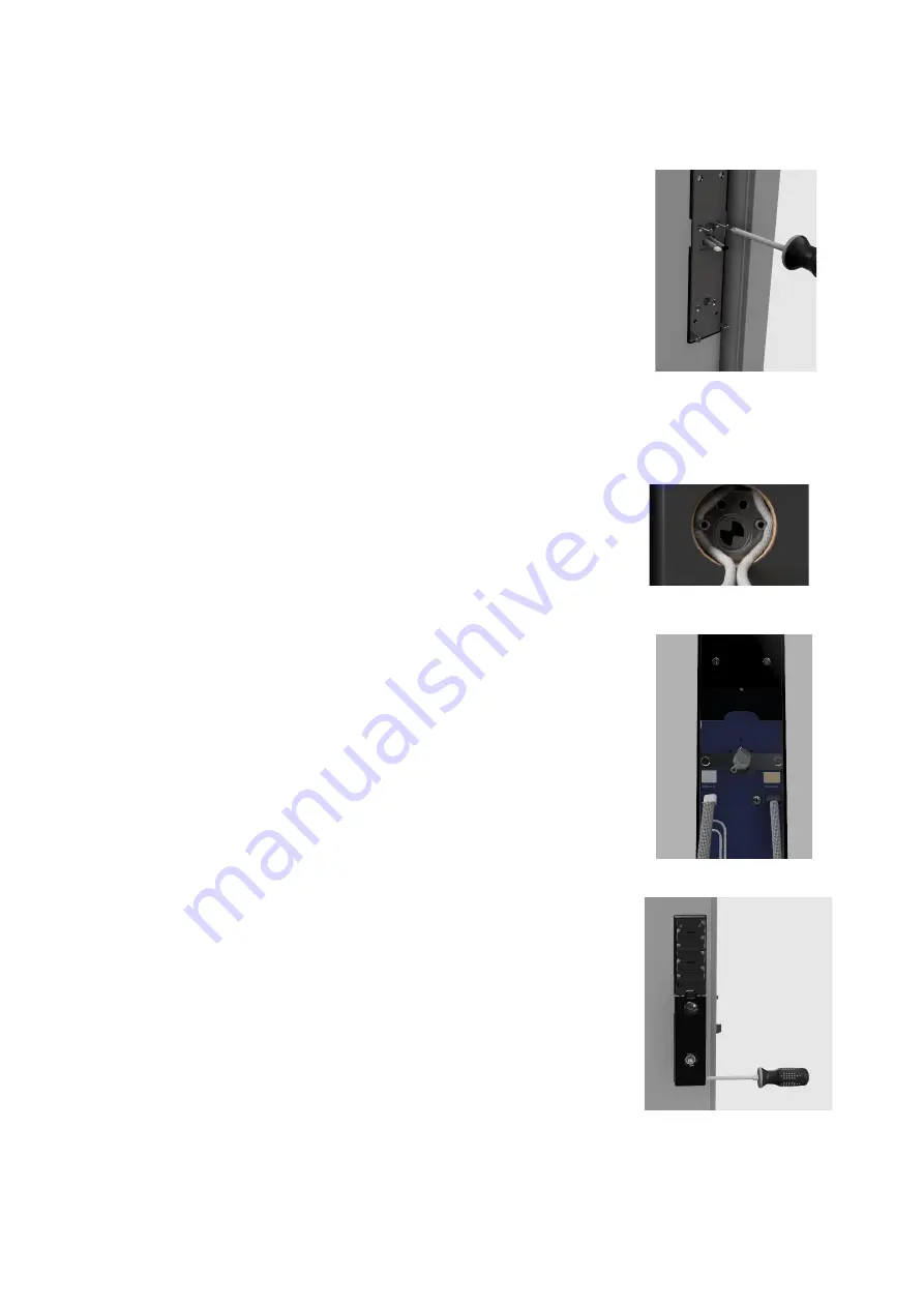
The back plate is fitted to the outside unit as shown in figure 8.
a.
The 4 cutting screws are cut to the correct thickness
according to the thickness of the door. Use medium-sized
pliers or a hacksaw to cut the screws.
Important! The screws must not be shorter than the
thickness of the door. Please try with one screw before
cutting the rest.
b.
The cables are fed through the opening marked on the
backing plate marked
«CABLE ENTRY»
.
c.
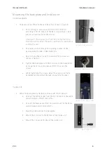
Be sure to lay the wires on the outside of the screws as
shown in figure 9.
d.
Tighten the backplate with the 4 screws so the backplate is
no longer bent. Use a screwdriver (PH2) to secure the
screws.
e.
While tightening the screws, adjust the exterior unit and
backplate to ensure that the lock is parallel to the door.
Inside unit
2.
When the backplate is attached, continue with the inside unit.
a.
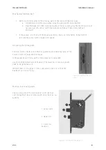
Connect the white socket from the mortise lock to the white
socket marked
«MORTISE LOCK»
b.
Connect the black socket from the outside unit to the beige
socket marked
«OUTSIDE UNIT»
c.
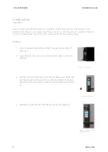
Place the inside unit on the backplate.
d.
Attach the 2 screws to the bottom of the inside unit.
e.
Attach the screws on the top of the inside unit.
Figure 8
–
Inside backplate
Figure 9
–
Cable positioning
Figure 10
–
Connecting cables
Figure 11
–
Attach inside unit


