


34
9. Programmer examples
In this application the rotation speed of an axis shall be collected via a toothed wheel with 30
sprockets, per Namur sensor. It is then displayed with one position after decimal point and the
dimension rpm.
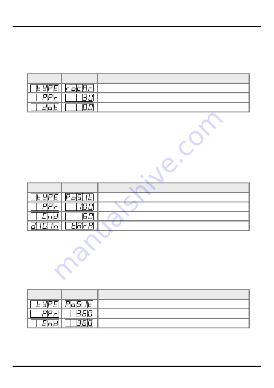
Parameter
Settings
Description
Rotation – rotation speed measurement up to 10 kHz
Number of sprockets
1 position after decimal point
Example for the rotation speed adjustment:
Advice:
The input frequency may be maximum 9.999 kHz in this operating module. So, a rotation
speed parameterisation via the frequency adjustment is rarely necessary.
Parameter
Settings
Description
Positioning – rotary encoder
Pulse number per rotation
Change of length per rotation
Display zero
A measuring system for length works via an incremental encoder with two dephased output
signals (typically A and B) and 100 pulse/rotation. The axis perimeter was calculated in a way that
the measuring section can be extracted by a rotation of 6 cm = 60 mm. The display shall show the
relative position in millimeter. There is a zero point position with a limit switch, that can zero the
display if required.
Example for the position coverage:
Advice:
The display starts always on position zero. The parameter
dig.in
can be found under
parameter group
–fct–
in the extended parameterisation
Prof
.
On a manually operated bender for sheet metal the bending angle shall be displayed in degree.
The device is in zero state (0°) during switching on of the display. An incremental encoder with
360 pulses/rotation is used.
Example for angle coverage:
Parameter
Settings
Description
Positioning – rotary encoder
Pulse number per rotation
Angle sum per rotation
9. Programmer examples


