


100
5.6.6 Network Information
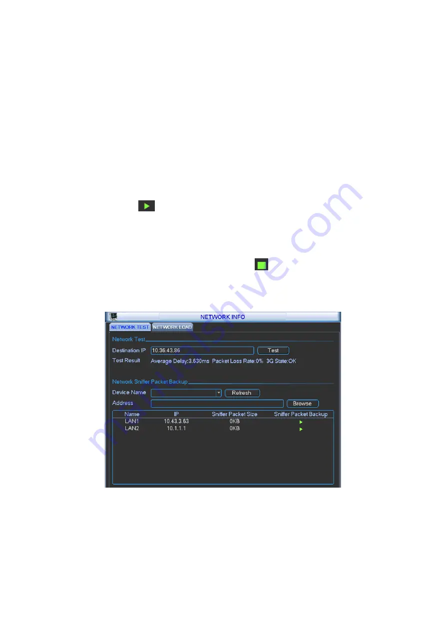
In this interface, you can see network test and network load information.
5.6.6.1 Network Test
Network test interface is shown as in Figure 5-73.
z
Destination IP: Please input valid IPV4 address and domain name.
z
Test: Click it to test the connection with the destination IP address. The test results can
display average delay and packet loss rate and you can also view the network status as OK,
bad, no connection and etc.
z
Network Sniffer backup: Please insert USB2.0 device and click the Refresh button, you can
view the device on the following column. You can use the dropdown list to select peripheral
device. Click Browse button to select the snap path. The steps here are same as preview
backup operation.
You can view all connected network adapter names (including Ethernet, PPPoE, WIFI, and 3G),
you can click the button
on the right panel to begin Sniffer. Click the grey stop button to stop.
Please note system can not Sniffer several network adapters at the same time.
After Sniffer began, you can exit to implement corresponding network operation such as login
WEB, monitor. Please go back to Sniffer interface to click
stop Sniffer. System can save the
packets to the specified path. The file is named after “Network adapter name+time”. You can use
software such as Wireshark to open the packets on the PC for the professional engineer to solve
complicated problems.
Figure 5-73
5.6.6.2 Network Load
Network load is shown as in Figure 5-74. Here you can view the follow statistics of the device
network adapter.
Here you can view information of all connected network adapters. The connection status is
shown as offline if connection is disconnected. Click one network adapter, you can view the flow
statistics such as send rate and receive rate at the top panel
Summary of Contents for N6 Series
Page 1: ...ICRealtime N6 Series Standalone DVR User s Manual Version 6 2 0 ...
Page 51: ...41 Figure 4 25 Figure 4 26 Figure 4 27 ...
Page 52: ...42 Figure 4 28 Figure 4 29 Figure 4 30 ...
Page 68: ...58 Figure 5 3 Figure 5 4 Figure 5 5 Figure 5 6 ...
Page 76: ...66 Figure 5 16 Figure 5 17 Figure 5 18 5 3 5 3 NTP Setup ...
Page 116: ...106 Figure 6 11 ...
Page 148: ...138 Figure 7 49 Figure 7 50 Figure 7 51 Figure 7 52 ...
Page 150: ...140 Figure 7 54 Figure 7 55 Figure 7 56 ...
Page 185: ...175 Maxtor DiamondMax 20 STM3250820AS 250G SATA ...


