36
B. Hardware Installation
B.1 Before Installation
The ICP Controller is designed for minimum power consumption and maximum operational
security. It therefore contains delicate electrical components (CMOS). In order to avoid
damages caused by electrostatic charges, the following warning must be observed during
installation:
Never take the ICP Controller out of the antistatic bag unless this is done at an anti-
static work place and the person handling the ICP Controller is secured against elec-
trostatic charge through wrist bands. If these instructions are not observed, the user
risks damage or destruction of the CMOS components of the ICP Controller !
B.2 Tools
Before installing, please switch off the complete computer system and remove all cables
including the power cable. Open the case of the host computer with an appropriate screw-
driver (usually a medium sized Philips screwdriver).
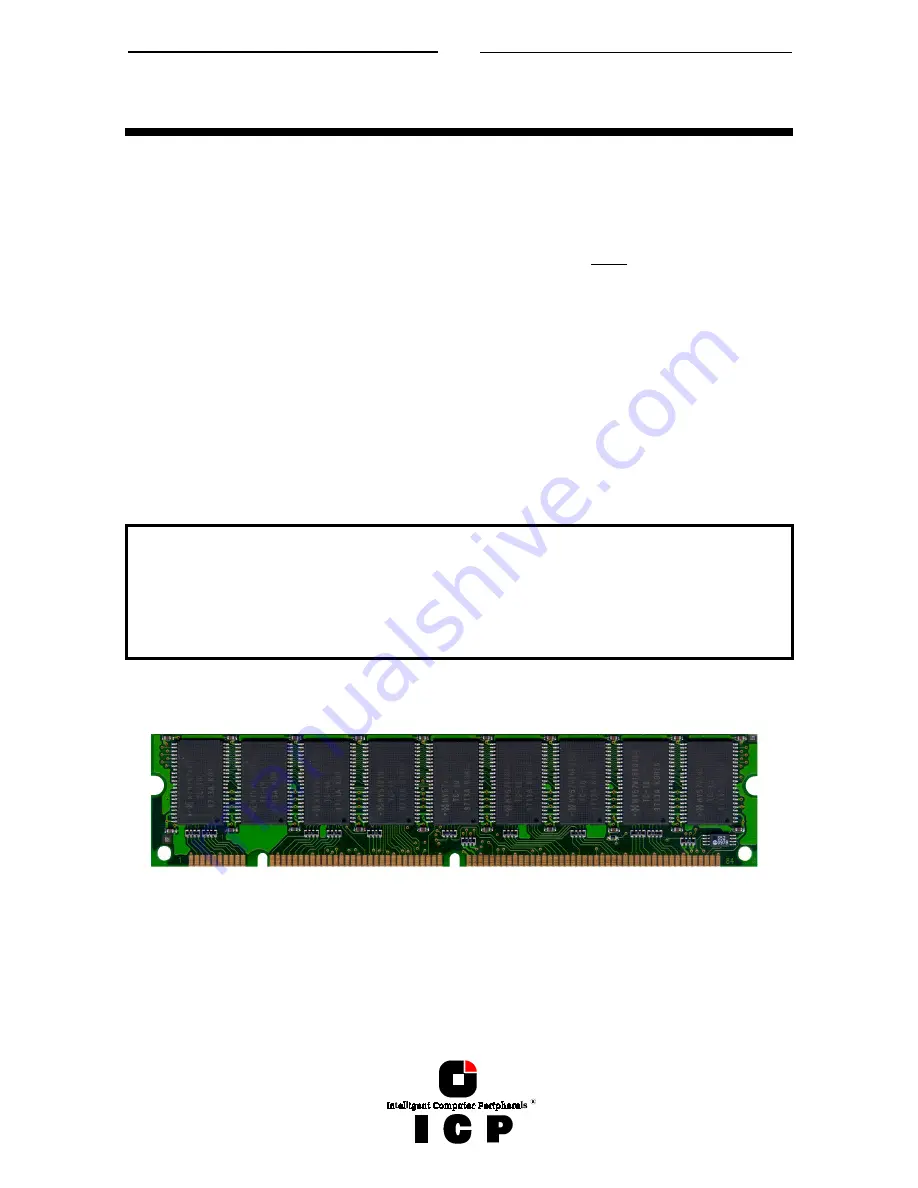
B.3 Installing the PC100 DIMM Module
It is not possible to operate the ICP Controller without PC100 DIMM
(Dual Inline Memory Module). The ICP Controller is delivered without
PC100 DIMM (0MB). The ICP Controller must be operated with one non-
buffered PC100 DIMM or one non-buffered ECC PC100 DIMM . The PC100
DIMM capacity can be 16MB, 32MB; 64MB or 128MB. The ICP Controller
can not be operated with buffered DIMMs.
If the ICP Controller is not yet equipped with cache RAM, or if another PC100 DIMM is to be
installed, we recommend adding it before you install the ICP Controller in your computer
system. As mentioned before, the ICP Controller can be run with four different cache RAM
sizes. The minimum cache RAM size is 16MB. The maximum cache RAM size is 128MB. The
ICP Controller provides one socket for a PC100 DIMM. The PC100 DIMM is correctly plugged
into the DIMM socket of the ICP Controller if it is engaged correctly into the socket's re-
taining clamps and if all contacts of the PC100 DIMM are equally contacting the corre-
sponding pins of the socket. To release an installed PC100 DIMM, carefully press the
retaining clamps to the side.
Each time you switch on the computer system, the ICP Controller automatically recognizes
how much cache RAM is available and configures itself accordingly.
Summary of Contents for GDT RS Series
Page 2: ...2...
Page 14: ...14 L 1 Technical Data of the ICP Controller 184 L 2 Boot Error Messages 184 L 3 Index 185...
Page 15: ...15 Chapter A General General General General Information Information Information Information...
Page 40: ...40 Example for a SCSI Flat Ribbon Cable for 8 Bit SCSI Devices narrow...
Page 41: ...41 Example for a SCSI Flat Ribbon Cable for 16 Bit SCSI Devices wide...
Page 47: ...47 Several internal Wide Ultra2 and Ultra 160 SCSI Hard Disks...
Page 52: ...52...
Page 53: ...53 Chapter C Quick Setup Quick Setup Quick Setup Quick Setup...
Page 68: ...68 Replacement either manually or through hot fix method...
Page 70: ...70...
Page 71: ...71 Chapter D Using MS DOS Using MS DOS Using MS DOS Using MS DOS...
Page 81: ...81 Chapter E Using NetWare Using NetWare Using NetWare Using NetWare...
Page 88: ...88...
Page 96: ...96...
Page 97: ...97 Chapter G Using LINUX Using LINUX Using LINUX Using LINUX...
Page 102: ...102...
Page 103: ...103 Chapter H Using SCO UNIX Using SCO UNIX Using SCO UNIX Using SCO UNIX...
Page 110: ...110...
Page 111: ...111 Chapter I Using UnixWare Using UnixWare Using UnixWare Using UnixWare...
Page 147: ...147 Chapter K ICP RAID Navigator ICP RAID Navigator ICP RAID Navigator ICP RAID Navigator...
Page 182: ...182...
Page 183: ...183 Chapter L Appendix Appendix Appendix Appendix...


