


M-4132 User Manual (Version 1.60, May/2014) PAGE:
8
2. Hardware
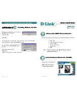
2.1 Pin Assignment
Figure 3: Pin assignment of M-4132
Table 1: 7-pin screw terminal block
Pin
Name
Description
1
T.GND
GND of trigger input
2
Trig
Trigger input
3
D+
Data+ of RS-485
4
D-
Data- of RS-485
5
PWR
V+ of Power Supply (+10 to +30VDC)
6
GND
GND of Power Supply
7
F.G.
Frame Ground