NeuroNexus SmartBox, Instruction Manual
The TCP SmartBox is a revolutionary home automation device that lets you control your lights and appliances easily. To get started, simply download the user manual from our website for free, where detailed instructions and guidelines are available for hassle-free setup and customization. manualshive.com is your go-to destination for downloading the manual.
Share
Download


Reviews:
No comments
Related manuals for SmartBox
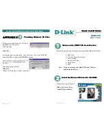
DSB-T100
Brand: D-Link Pages: 2

M44
Brand: DAS Pages: 16

Caruso
Brand: T+A Pages: 56
M-4132
Brand: ICP DAS USA Pages: 70
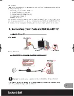
Medi TV
Brand: Packard Bell Pages: 48
Adagio ATC-AMFM2
Brand: Crestron Pages: 20

DIS-1/S
Brand: dallmeier Pages: 97
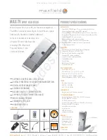
MAX-TV
Brand: Maxfield Pages: 3
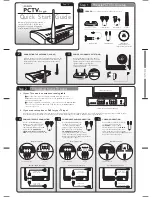
PCTV 300I
Brand: Pinnacle Pages: 14
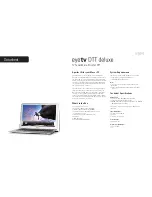
EyeTV DTT DELUXE
Brand: Elgato Pages: 1
PCTV To Go
Brand: Pinnacle Pages: 2
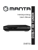
DVBT03
Brand: Manta Pages: 28

HS-1600T-2C140TM
Brand: Datavideo Pages: 63
WinTV-USB2
Brand: Hauppauge Pages: 2
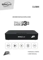
RICD1232
Brand: DiGiQuest Pages: 54
Colosseum 8500D
Brand: Johansson Pages: 28
BVTS4
Brand: Boss Audio Systems Pages: 9

AVerTV MCE 116 Plus
Brand: Avermedia Pages: 1


