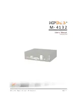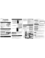

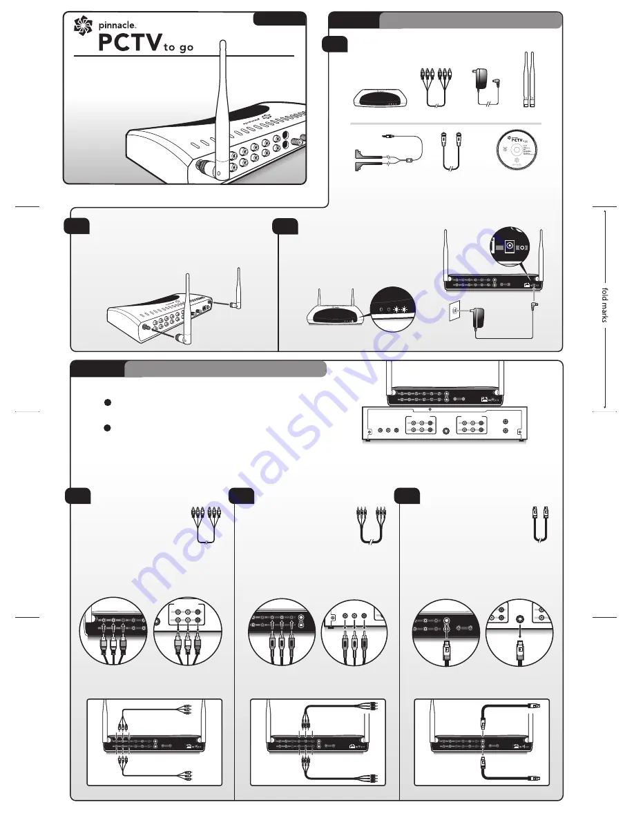
CONNECTING THE ANTENNAS (2.4 GHZ)
Hold the antenna at its base and gently twist each onto the
threaded jack connectors on either side of the back of your
Pinnacle PCTV To Go. Adjust the ends of the antenna to
point upwards.
POWER UP PINNACLE PCTV TO GO
Connect the power cord to the back of
your Pinnacle PCTV To Go and the power
adapter to a power source. Wait until the 2
rightmost LEDs are solid green.
Pinnacle PCTV To Go is then ready for
setup and operation.
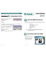
Step 1 Pinnacle PCTV To Go
setup
2
1
3
UNPACK:
Check that your package includes the following:
Unit ready
Coaxial/RF cable
Power adapter
IR blaster cable
CD-ROM with
Pinnacle PCTV To Go
software and documentation
Antennas
Composite cable
Pinnacle PCTV To Go
COMPOSIT
E VIDEO
COMPONENT VIDEO
ANTENNA IN
ETHERNET
12VDC 3A
IR BLASTER
ANTENNA OUT
WLAN ANTENNA #1
WLAN ANTENNA #2
AUDIO LEFT
AUDIO RIGHT
S-VIDEO
Y
Pb
Pr
IN
OUT
IN
OUT
ETHERNET
9VDC 2A
IR BLASTER
WLAN ANTENNA #2
ETHERNET
12VDC 3A
IR BLASTER
WLAN ANTENNA #2
ANTENNA OUT
COMPONENT VIDEO
ANTENNA IN
AUDIO RIGHT
S-VIDEO
Y
Pb
Pr
IN
OUT
COMPOSIT
E VIDEO
WLAN ANTENNA #1
AUDIO LEFT
IN
OUT
ETHERNET
12VDC 3A
IR BLASTER
WLAN ANTENNA #2
ANTENNA OUT
COMPONENT VIDEO
ANTENNA IN
AUDIO RIGHT
S-VIDEO
Y
Pb
Pr
IN
OUT
COMPOSIT
E VIDEO
WLAN ANTENNA #1
AUDIO LEFT
IN
OUT
ETHERNET
12VDC 3A
IR BLASTER
WLAN ANTENNA #2
ANTENNA OUT
COMPONENT VIDEO
ANTENNA IN
AUDIO RIGHT
S-VIDEO
Y
Pb
Pr
IN
OUT
COMPOSIT
E VIDEO
WLAN ANTENNA #1
AUDIO LEFT
IN
OUT
A
Step 2 Connecting to your TV signal
Direct Connection
Direct Connection
Direct Connection
COMPOSIT
E VIDEO
COMPONENT VIDEO
ANTENNA IN
ETHERNET
12VDC 3A
IR BLASTER
ANTENNA OUT
WLAN ANTENNA #1
WLAN ANTENNA #2
AUDIO LEFT
AUDIO RIGHT
S-VIDEO
Y
Pb
Pr
IN
OUT
IN
OUT
VIDEO
ANT/CATV IN
ANT/CATV OUT
AUDIO LEFT
AUDIO RIGHT
IN
1
2
S-VIDEO OUT
VIDEO
AUDIO LEFT
AUDIO RIGHT
1
2
AUDIO-VIDEO INPUTS
AUDIO-VIDEO OUTPUTS
Y
Pb
Pr
PINNACLE PCTV TO GO
CABLE SET-TOP / SATELLITE / DVR BOX
Pinnacle PCTV To Go
Device
Pinnacle PCTV To Go
Device
Pinnacle PCTV To Go
Device
In from Cable,
Satellite or DVR box
In from Cable,
Satellite or DVR box
Pass-through Connection
Pass-through Connection
Pass-through Connection
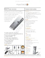
B
COMPOSIT
E VIDE
O
COMPONENT VIDEO
WLAN ANTENNA #1
AUDIO LEFT
AUDIO RIGHT
S-VIDEO
Y
Pb
Pr
IN
OUT
VIDEO
ANT/CATV IN
ANT/CATV OUT
AUDIO LEFT
AUDIO RIGHT
IN
1
2
S-VIDEO OUT
VIDEO
AUDIO LEFT
AUDIO RIGHT
1
2
AUDIO-VIDEO INPUTS
AUDIO-VIDEO OUTPUTS
Y
Pb
Pr
COMPOSITE CABLE CONNECTION
Use the included
Composite
Cable
to connect one end from
the available outputs on your
cable/satellite/DVR box to the
IN
inputs labeled
COMPOSITE
VIDEO, AUDIO LEFT, and AUDIO
RIGHT
on your Pinnacle PCTV To Go.
COMPONENT CABLE CONNECTION
Use a
Component cable
(not
included) to connect one end
from the available
Y, Pb, Pr
outputs on your cable/satellite/
DVR box to the corresponding
COMPONENT VIDEO
inputs on
your Pinnacle PCTV To Go. For audio,
follow the connection settings for the
Composite connection (Option A), but don’t
connect the video input.
C
S-VIDEO CONNECTION
Use an
S-Video cable
(not included)
to connect one end from the
S-VIDEO OUT
on your cable/
satellite/DVR box to the
S-VIDEO IN
on your Pinnacle PCTV To Go. For
audio, follow the connection settings
for the Composite connection (Option A), but
don’t connect the video input.
COMPONENT VIDEO
ANTENNA IN
ETHERNET
ANTENNA OUT
AUDIO LEFT
AUDIO RIGHT
S-VIDEO
Y
Pb
Pr
IN
OUT
VIDEO
AUDIO LEFT
AUDIO RIGHT
IN
1
2
S-VIDEO OUT
VIDEO
AUDIO LEFT
AUDIO RIGHT
1
2
AUDIO-VIDEO INPUTS
AUDIO-VIDEO OUTPUTS
Y
Pb
Pr
IN
OUT
VIDEO
ANT/CATV IN
ANT/CATV OUT
AUDIO LEFT
AUDIO RIGHT
IN
1
2
S-VIDEO OUT
VIDEO
AUDIO LEFT
AUDIO RIGHT
1
2
AUDIO-VIDEO INPUTS
AUDIO-VIDEO OUTPUTS
Y
Pb
Pr
COMPOSIT
E VIDEO
COMPONENT VIDEO
WLAN ANTENNA #1
AUDIO LEFT
AUDIO RIGHT
S-VIDEO
Y
Pb
Pr
IN
OUT
Out to TV, VCR
or DVD recorder
In from Cable,
Satellite or DVR box
Out to TV, VCR
or DVD recorder
Out to TV, VCR
or DVD recorder
1
Disconnect the current incoming Coaxial/RF cable from your TV’s
RF/Antenna In
connector and reconnect it to the
Antenna In
connector of
your Pinnacle PCTV To Go.
2
Using the supplied Coaxial/RF cable, connect one end to the
Antenna Out
connector of your Pinnacle PCTV To Go and the other to the
RF/Antenna In
connector of your TV.
If your TV source is an antenna or analog cable
Choose one of the 3 following connection options. If you don’t have the available outputs required, you can use the pass-through connections of PCTV To Go as
described below. Note that the connectors may be positioned differently on your PCTV To Go than they are pictured here.
If you use a set-top box or DVR for your TV input
A.
B.
41007283 R1
251006
Quick Start Guide
Welcome! Thank you for purchasing a
Pinnacle PCTV
To Go. Follow these
instructions to quickly start playing
your TV anywhere on your PC.
Vers. 1.0
TM
Fold to 16 panels
TOP
Bottom
This panel will be the the front panel Final size is 5.534” x 4.2852”