background image


GPS-721  User  Manual 

17/98

    GPS-721  User  Manual  V2.0,  Oct.  2010
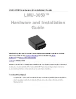
 

Rear View 

1.5 

Dimensions


ГК


Атлант


Инжиниринг

 – 

официальный


представитель


в


РФ


и


СНГ


+7(495)109-02-08 [email protected] www.bbrc.ru 

Summary of Contents for GPS-721

Page 1: ...GPS 721 User Manual 1 98 GPS 721 User Manual V2 0 Oct 2010 GPS 721 User Manual v2 0 High quality Industrial Data Acquisition and Control Products 7 495 109 02 08 sales bbrc ru www bbrc ru...

Page 2: ...manual at any time without notice The information furnished by ICP DAS is believed to be accurate and reliable However no responsibility is assumed by ICP DAS for its use or for any infringements of p...

Page 3: ...s 13 1 4 5 Wiring Recommendations 14 1 5 Wiring 15 1 6 Dimensions 17 1 7 Mounting 18 1 8 Frame Ground 20 1 9 Configuration Table 22 1 10 Quick start 23 1 11 Technical Support 25 2 DCON Protocol 26 2 1...

Page 4: ...me 68 2 21 AAD 70 2 22 AADVV 72 2 23 AAI 74 2 24 AAM 76 2 25 AAMN 78 2 26 AATnn 81 2 27 84 2 28 AA0 85 2 29 AA1 87 2 30 AA2 89 2 31 AA3EVV 91 2 32 AA4V 93 2 33 AA5V 95 A 1 Dual Watchdog Operation 97 A...

Page 5: ...ide GPS module is powered by MediaTek solution and it can provide you with superior sensitivity and performance even in urban canyon and dense foliage environment Except for the GPS data GPS 721 inclu...

Page 6: ...col Built in 1 channel DO 1 channel PPS 1 pulse per second 1 RS 485 port and 1 RS 232 port PPS 100 ms pulse output sec for precise timekeeping and time measurement 10 30V DC Power reverse polarity pro...

Page 7: ...tity GPS 721 1 External GPS antenna ANT 115 03 Length 5m 1 RS 232 Cable CA 0910 1 Product CD 1 Quick Start Guide 1 Please check that these items and contained in your GPS 721 package If there are any...

Page 8: ...GPS 721 User Manual 8 98 GPS 721 User Manual V2 0 Oct 2010 Number of satellites LED INIT Normal Switch Hardware 7 495 109 02 08 sales bbrc ru www bbrc ru...

Page 9: ...ion 3 01 GPS Antenna default Length 5 m Frequency Range 1575 42 1 023 MHz Gain At 90 30 4 5dBi cable loss Mounted on the 60mm 60mm ground plane Output Impedance 50 VSWR 2 0 Max GPS Output 1 PPS Pulse...

Page 10: ...ating Temperature 25 C 75 C Storage Temperature 40 C 80 C Humidity 5 95 RH non condensing I O specification Digital Output Output Channel 1 Sink Output Type Non isolated Open Collector Output Current...

Page 11: ...GPS 721 User Manual 11 98 GPS 721 User Manual V2 0 Oct 2010 1 3 2 Block Diagram for the GPS 721 7 495 109 02 08 sales bbrc ru www bbrc ru...

Page 12: ...O1 OFF Digital Output is off ON The number of signals received from GPS satellites is less than 5 S1 OFF Module can t receive any GPS signals ON The number of signals received from GPS satellites is 5...

Page 13: ...ion Init After setting the module to INIT mode and restart the module a connection can be established using the default module address and communication settings allowing new parameters for the module...

Page 14: ...12 AWG wire for signal connections Strip the wire to a length of 7 0 5mm Use a crimp terminal for wiring Avoid high voltage cables and power equipment as much as possible For RS 485 communication use...

Page 15: ...GPS 721 User Manual 15 98 GPS 721 User Manual V2 0 Oct 2010 1 4 Wiring DO wiring PPS wiring 7 495 109 02 08 sales bbrc ru www bbrc ru...

Page 16: ...s Note A Pulse per second PPS is an electrical signal that very precisely indicates the start of a second PPS signals can be used for precise timekeeping and time measurement one can combine the PPS f...

Page 17: ...GPS 721 User Manual 17 98 GPS 721 User Manual V2 0 Oct 2010 Rear View 1 5 Dimensions 7 495 109 02 08 sales bbrc ru www bbrc ru...

Page 18: ...mounting on a standard 35 mm DIN rail There are three new DIN rail models available Each is made of stainless steel which is stronger than those made of aluminum There is a screw at one end and a ring...

Page 19: ...nual V2 0 Oct 2010 Piggyback Mounting The GPS 721 has two holes on both sides of the module to enable piggyback mounting Refer to the figure below for an illustration of how to piggyback the modules 7...

Page 20: ...lowing enhanced static protection ESD capabilities and ensures that the module is more reliable Either of the following options will provide a better protection for the module 1 If the module is DIN r...

Page 21: ...connected to the earth ground Each is made of stainless steel which is stronger than those made of aluminum There is a screw at one end and a ring terminal is included as shown in the figure below Re...

Page 22: ...d Rate Setting CC Code 03 04 05 06 07 08 09 0A Baud Rate 1200 2400 4800 9600 19200 38400 57600 115200 Type Code Setting TT Type Code is fixed as 40 Data Format Setting FF 7 6 5 4 3 2 1 0 0 CS 0 0 Key...

Page 23: ...ntenna 2 Connect the module to the RS 485 network using the DATA and DATA terminals See Section 1 4 3 for details of the terminal assignment If the host is only equipped with an RS 232 interface then...

Page 24: ...operating system installed the DCON Utility can be used to allow easy configuration and reading of data The DCON Utility can be downloaded from the ICP DAS website http www icpdas com The documentati...

Page 25: ...e module 2 Firmware version See Section 2 15 for information regarding the command used to identify the firmware version 3 Host configuration type and operating system 4 If the problem is reproducible...

Page 26: ...contain the ID address meaning that only the addressed module will respond The only exception to this is commands Section 2 2 and Section 2 27 which are sent to all modules but in both of these cases...

Page 27: ...ple Command string 012 CR 1 Sum of the string 0 1 2 24h 30h 31h 32h B7h 2 Therefore the checksum is B7h and so CHKSUM B7 3 The command string with the checksum 012B7 CR Response string 01200600 CR 1 S...

Page 28: ...t 2 5 AA0A Data Sets the Digital Output 2 6 AA1c Data Sets the Digital Output 2 7 AAAc Data Sets the Digital Output 2 8 AA2 AANNTTCCFF Reads the Module Configuration 2 9 AA4 S Data Reads the Synchroni...

Page 29: ...ion mode of the module to either NMEA 0183 or DCON 2 25 AATnn AA Sets the soft INIT timeout value 2 26 Host WatchDog Command Sets Command Response Description Section No Response Host OK The address i...

Page 30: ...he module in hexadecimal format 00 to FF TT Type Code Refer to Section 1 9 configuration table The type Code of the GPS 721 is fixed as 40 CC Refer to the module section 1 9 configuration table The Ba...

Page 31: ...dress from 01 as 09 The response 09 indicates that the command is valid Command 092 Response 09400600 Success to read the configuration of this module Command 0905400940 Response 05 Changes the Baud R...

Page 32: ...um settings take effect on the next power on reset 2 In order to chang the Baud Rate checksum settings or others the module needs to be in Init mode Another way is to send the following commands befor...

Page 33: ...Command There is no response with this command To access the data another command AA4 must be sent Examples Command Response No response Sends the synchronized sampling command to all modules Command...

Page 34: ...on 2 10 AA4 Command 014 Response 0060000 Sends a command to read the synchronized data The status byte of the response is 0 which means that it is NOT the first time the synchronized data has been rea...

Page 35: ...the module in hexadecimal format 00 to FF Response Valid Command AATTTTTT TTT LLLL LLLL C NNNNN NN NN C P S Delimiter for a valid command Delimiter for an invalid command AA Address of the module in...

Page 36: ...he data will be set as 9 Examples Command 01 Response 01999999 999 9999 9999 9 99999 9999 9 0 00 Reads the UTC time latitude longitude mode and number of satellites in view for a module and the module...

Page 37: ...er character AA Address of the module in hexadecimal format 00 to FF N 1 UTC Time 2 Latitude and longitudes 3 Number of Satellites in view 4 Date Response N 1 AATTTTTT TTT N 2 AALLLL LLLL C NNNNN NNNN...

Page 38: ...th Y year If there are not enough GPS satellite signals the data will be set as 9 Examples Command 011 Response 01999999 999 Reads the UTC time of module 01 and the module returns a valid response The...

Page 39: ...ct 2010 Related Commands Section 2 3 AA Section 2 13 AAD Command 014 Response 01280308 Indicates that the current date is 3 28 2008 The AAD command needs to be sent to update the date before using thi...

Page 40: ...er eight channels Data A two digit hexadecimal value Bit 0 corresponds to DO0 and Bit 1 corresponds to DO1 A bit value 1 of denotes that the digital output channel is on and a bit value of 0 denotes t...

Page 41: ...nse Sets DO0 of the module with address 01 and the module returns a valid response Command 010016 Response 01 Sets DO0 and DO3 to Off DO1 and DO2 to On DO6 DO7 and DO8 to Off and DO5 to On This module...

Page 42: ...ta A two digit hexadecimal value Bit 0 corresponds to DO0 and Bit 1 corresponds to DO1 A bit value 1 of denotes that the digital output channel is on and a bit value of 0 denotes that the digital outp...

Page 43: ...0A01 Response Sets the DO0 of the module with address 01 to On and the module returns a valid response Command 010A01 Response A Host WatchDog Timeout was occurred and so the DO output command is igno...

Page 44: ...put channel for the lower eight channels c Specifies the digital output channel to be set ranging from 0 to 7 DD 00 sets the digital output channel to off 01 sets the digital output channel to on Resp...

Page 45: ...Response Sets the DO0 of the module with address 01 to On and the module returns a valid response Command 011400 Response 01 Sets DO4 to Off This module only include on DO0 channel so the command is i...

Page 46: ...tput channel for the lower eight channels c Specifies the digital output channel to be set ranging from 0 to 7 DD 00 set the digital output channel to off 01 set the digital output channel to on Respo...

Page 47: ...ponse Sets the DO0 of the module with address 01 to On and the module returns a valid response Command 01A000 Response Sets the DO0 of the module with address 01 to Off and the module returns a valid...

Page 48: ...ration Response Valid Command AATTCCFF CHKSUM CR Invalid Command AA CHKSUM CR Delimiter for a valid command Delimiter for an invalid command AA Address of the module in hexadecimal format 00 to FF TT...

Page 49: ...s no module with the specified address Related Commands Section 1 9 Configuration Table Examples Command 012 Response 01400A00 Reads the configuration of module 01 BaudRate 115200 Checksum Disabled Co...

Page 50: ...e in hexadecimal format 00 to FF 4 Command to read the synchronized data Response Valid Command S CHKSUM CR Invalid Command AA CHKSUM CR Delimiter for a valid command Delimiter for an invalid command...

Page 51: ...ommand 014 Response 1010000 Reads the synchronized data for module 01 The module returns the synchronized data and sets the status byte to 1 to indicate that this is the first time the synchronized da...

Page 52: ...mand AAS CHKSUM CR Invalid Command AA CHKSUM CR Delimiter for a valid command Delimiter for an invalid command AA Address of the module in hexadecimal format 00 to FF S The reset status of the module...

Page 53: ...cified address Examples Command 035 Response 031 Reads the reset status of module 03 The response shows that it is the first time the AA5 command has been sent since the module was powered on Command...

Page 54: ...channels Syntax AA6 CHKSUM CR Delimiter character AA Address of the module in hexadecimal format 00 to FF 6 Command to read the digital input output channels Response Valid Command AA Data CHKSUM CR...

Page 55: ...which denotes that the Digital Output is on Command 076 Response 07 Reads the digital input output channel status of module 07 The command is invalid became no module with the specified address exits...

Page 56: ...clear the status of the latched digital output channel Syntax AAC CHKSUM CR Delimiter character AA Address of the module in hexadecimal format 00 to FF C Command to clear the status of the latched dig...

Page 57: ...the latched digital output channels of module 01 and returns a valid response Command 01L0 Response 010 Sends a command to read the status of the low latched digital output channel of module 01 and r...

Page 58: ...rent date of the module Command AA4 is use to read the current date It takes 2 seconds to read the date Syntax AAD CHKSUM CR Delimiter character AA Address of the module in hexadecimal format 00 to FF...

Page 59: ...2 0 Oct 2010 Related Commands Examples Command 01D Response 01 Updates the current date and temporarily saves the date in the module Command 014 Response 0199 99 9999 Reads the current date Section 2...

Page 60: ...R Delimiter character AA Address of the module in hexadecimal format 00 to FF F Command to read the firmware version Response Valid Command AA Data CHKSUM CR Invalid Command AA CHKSUM CR Delimiter for...

Page 61: ...HKSUM CR Delimiter character AA Address of the module in hexadecimal format 00 to FF M Command to read the module name Response Valid Command AA Data CHKSUM CR Invalid Command AA CHKSUM CR Delimiter f...

Page 62: ...KSUM CR Delimiter character AA Address of the module in hexadecimal format 00 to FF L Command to read the latched status S 0 Reads the low latched status 1 Reads the high latched status Response Valid...

Page 63: ...e 01 Clears the latched status of a DO channel Command 01L0 Response 010 Sends a command to read the status of the low latched digital output channel of module 01 and return 0 Command 01L1 Response 01...

Page 64: ...ports Syntax AA CHKSUM CR Delimiter character AA Address of the module in hexadecimal format 00 to FF Response Valid Command Data CHKSUM CR Invalid Command AA CHKSUM CR Delimiter for a valid command...

Page 65: ...0 Reads the digital input output port status of module 01 Response 0100 where 01 is the status of the DO channel Related Commands Section 2 5 AA00 Data Section 2 6 AA0A Data Section 2 7 AA1cDD Section...

Page 66: ...le digit hexadecimal value Bit 0 of the value corresponds to the DO channel A bit value of 1 denotes that the digital output channel is on and a bit value of 0 denotes that the digital output channel...

Page 67: ...d Commands command will be ignored Examples Command 011 Response Sets the DO channel of the module to On The response indicates that the command was successful Command 019 Response 01 The output value...

Page 68: ...sed to set the name of the module Syntax AAO Name CHKSUM CR Delimiter character AA Address of the module in hexadecimal format 00 to FF O Command to set the module name Name The new name of the module...

Page 69: ...se 01GPS721 Reads the name of module 01 and returns the name GPS721 Command 01O87000 Response 01 Sets the name of module 01 to 87000 and returns a valid response Command 01M Response 0187000 Reads the...

Page 70: ...aracter AA Address of the module in hexadecimal format 00 to FF D Command to read the DO Active status Response Valid Command AAVV CHKSUM CR Invalid Command AA CHKSUM CR Delimiter for a valid command...

Page 71: ...tput value 1 indicates that the relay is inactive There will be no response if the command syntax is incorrect there is a communication error or there is no module with the specified address Related C...

Page 72: ...AA Address of the module in hexadecimal format 00 to FF D Command to set the miscellaneous settings VV Two hexadecimal digits that represent the miscellaneous settings as follows shown below 00 02 Res...

Page 73: ...utput value 1 indicates that the relay is inactive There will be no response if the command syntax is incorrect there is a communication error or there is no module with the specified address Related...

Page 74: ...command can then be used to set the duration of the Soft INIT mode During that time can be changed the BaudRate and checksum of the module by using the AANNTTCCFF command See Section 2 1 Syntax AAI CH...

Page 75: ...sing the AATnn command the module returns an invalid response Command 01T10 Response 01 Sends a command to set the Soft INIT duration to 16 0x10 seconds The module returns a valid response Command 01I...

Page 76: ...Delimiter character AA Address of the module in hexadecimal format 00 to FF M Command to read the transmission mode of RS 232 port Response Valid Command AASC CHKSUM CR Invalid Command AA CHKSUM CR De...

Page 77: ...ts both DCON and GPS modes The protocol is the DCON protocol Command 03M1 Response 03 Sets the transmission mode to GPS mode and returns a valid response This command needs the module to be set to INI...

Page 78: ...nt via the RS 485 port Syntax AAMN CHKSUM CR Delimiter character AA Address of the module in hexadecimal format 00 to FF M Command to set the transmission protocol N Code to indicate the transmission...

Page 79: ...CON and GPS modes The protocol is DCON mode Command 03M1 Response 03 Sets the transmission mode to GPS protocol and the module returns a valid response This command needs the module to be set to INIT...

Page 80: ...ated Commands Command 03M1 Response 03 Sets the transmission mode to GPS protocol and the module returns an invalid response Before changing the communication protocol module needs to be set to INIT m...

Page 81: ...See Section 2 1 Syntax AATnn CHKSUM CR Delimiter character AA Address of the module in hexadecimal format 00 to FF T Command to set the Soft INIT duration nn Two hexadecimal digits that represent the...

Page 82: ...s a valid response Command 0107400780 Response 01 Sends a command to change the BaudRate and checksum The module returns an invalid response because the AATnn command has not been used to set the Soft...

Page 83: ...ct 2010 Related Commands Command 0107400740 Response 01 After sending the AATnn and AAI commands this command can be used to change the BaudRate and checksum The module returns a valid response Sectio...

Page 84: ...module would enter safe mode without receiving command during WatchDog timeout to avoid unexpected accident Syntax CHKSUM CR Delimiter character Host OK command Response Valid Command No response Exam...

Page 85: ...sponse Valid Command AASS CHKSUM CR Invalid Command AA CHKSUM CR Delimiter for a valid command Delimiter for an invalid command AA Address of the module in hexadecimal format 00 to FF SS Two hexadecim...

Page 86: ...d Commands WatchDog timeout has occurred Examples Command 010 Response 0104 Reads the Host WatchDog status of module 01 and the response shows that a Host WatchDog timeout has occurred Command 070 Res...

Page 87: ...eset the Host WatchDog timeout status of a module Syntax AA1 CHKSUM CR Delimiter character AA Address of the module in hexadecimal format 00 to FF 1 Command to reset the Host WatchDog timeout status R...

Page 88: ...01 and the response shows that a Host WatchDog timeout has occurred Command 071 Response 07 Resets the Host WatchDog timeout status of module 07 and the module returns a valid response Section 2 27 S...

Page 89: ...the Host WatchDog timeout value Response Valid Command AAEVV CHKSUM CR Invalid Command AA CHKSUM CR Delimiter for a valid command Delimiter for an invalid command AA Address of the module in hexadeci...

Page 90: ...ified address Related Commands Example Command 012 Response 011FF Reads the Host WatchDog timeout value of module 01 and returns a value of 64 which denotes that the Host WatchDog is enabled and the H...

Page 91: ...ess of the module in hexadecimal format 00 to FF 3 Command to set the Host WatchDog E 1 enables the Host WatchDog 0 disables the Host WatchDog VV Two hexadecimal digits to represent the timeout value...

Page 92: ...f module 01 and sets the Host WatchDog timeout value to 10 0 seconds The module returns a valid response Command 010 Response 0104 Reads the Host WatchDog status of module 01 and shows that a Host Wat...

Page 93: ...value of the module Syntax AA4V CHKSUM CR Delimiter character AA Address of the module in hexadecimal format 00 to FF 4 Command to read the power on DO value or the safe DO value V P Power on DO Valu...

Page 94: ...Commands Examples Command 014P Response 011 Reads the power on DO value of module 01 and the module returns a value of 1 Command 014S Response 010 Reads the safe DO value of module 01 and the module r...

Page 95: ...e as the power on DO value or the safe DO value Syntax AA5V CHKSUM CR Delimiter character AA Address of the module in hexadecimal format 00 to FF 5 Command to set the power on DO value or the safe DO...

Page 96: ...module returns 5500 which denotes that the safe DO value is 0 Related Commands Examples Command 015P Response 01 Sets the power on DO value and the module returns a valid response Command 011 Response...

Page 97: ...rs the operating status of the host Its purpose is to prevent problems due to network communication errors or host malfunctions When a Host WatchDog timeout occurs the module will reset all outputs to...

Page 98: ...minor drawback is that there are no visual indications of the configuration of the module New I 7000 and M 7000 modules include node information areas that are protected by a cover as shown below and...

Reviews: