ICP DAS USA ECAT-2094P User Manual Download Page 65


65 


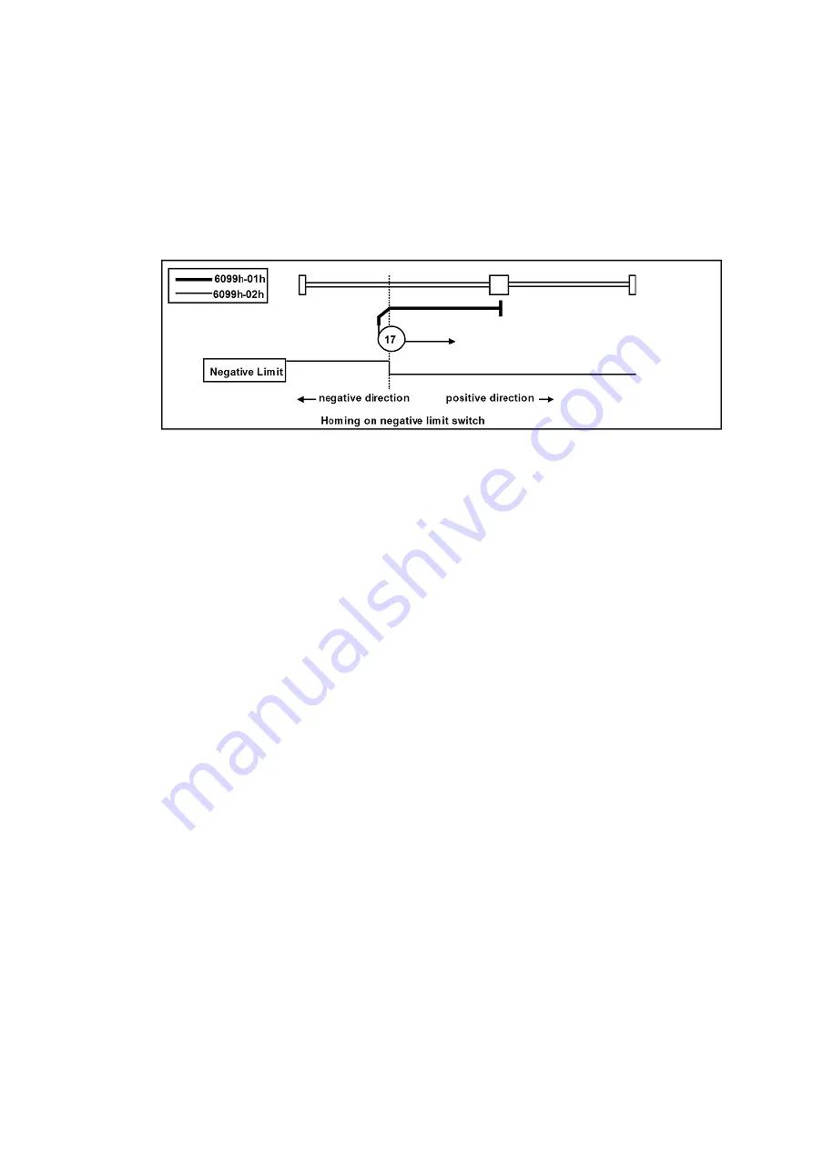
Method 17 


If LL switch is not activated at the beginning of the action, the initial action 
direction is the negative direction. 


If the LL switch has been activated at the beginning of the action, the initial 
action direction is the positive direction. 


The home detection position is the position when the status of LL changes. 


Summary of Contents for ECAT-2094P

Page 1: ...ECAT 2094P EtherCAT 4 Axis Pulse Output Module User Manual Version 1 0...

Page 2: ...e The information furnished by ICP DAS is believed to be accurate and reliable However no responsibility is assumed by ICP DAS for its use nor for any infringements of patents or other rights of third...

Page 3: ...h 1FFFh 25 4 1 Device information 25 4 2 PDO Process Data Object Mapping 27 4 2 1 PDO Assign Object 1C12h 1C13h 27 4 2 2 PDO Mapping Object 1600h 1630h 1A00 1A30h 27 4 3 Sync manager 2 3 sychronizatio...

Page 4: ...ofile Position Mode pp mode 51 6 6 3 Cyclic Synchronous Position Mode csp mode 54 6 6 4 Homing Mode hm mode 56 6 7 Velocity Control Function 72 6 7 1 Cyclic Synchronous Velocity Mode csv mode 72 7 Ala...

Page 5: ...o be done by the EtherCAT master and the application program The ECAT 2094P has four integrated incremental encoder interfaces Four 32 bit high frequency encoder counter counts the input signal of ext...

Page 6: ...I O EtherCAT and motion status Internal memory for storing configuration data EtherCAT 2 x RJ 45 bus interface Distance between stations up to 100 m 100BASE TX Support daisy chain connection EtherCAT...

Page 7: ...tus Digital IO Communication Interface Connector 2 x RJ 45 Protocol EtherCAT Distance between stations Max 100 m 100BASE TX Data transfer medium Ethernet EtherCAT Cable Min CAT 5 Shielded Power Input...

Page 8: ...ate Single flash Device is in SAFEOP state Outputs remain in safe state On Device is in OP state IN green Indicates the communication status of the EtherCAT port IN Off No connection Flashing Link and...

Page 9: ...5 AXIS Y Alarm Code Bit1 LED 6 AXIS Y Alarm Code Bit2 LED 7 AXIS Y Alarm third row 16 17 18 19 20 21 22 23 green LED 0 AXIS Z Home Switch input LED 1 AXIS Z Positive direction hardware limit input LED...

Page 10: ...10 2 2 Alias Rotary Swtich The Alias range is 0x00 0xFF...

Page 11: ...er contact IN EtherCAT signal input Incoming EtherCAT cable OUT EtherCAT signal output Outgoing EtherCAT cable Name Signal Description PGND Ground 0V from negative power contact Power supply to encode...

Page 12: ...for motor X Y_P Output Pulse Signal CW Signal Pulse Y Y_P Output Pulse Signal CW Signal Y_N Output Dir Signal CCW Signal Y_N Output Dir Signal CCW Signal Y_A Input Encoder Y input A Encoder Y Y_A Inpu...

Page 13: ...for motor Z U_P Output Pulse Signal CW Signal Pulse U U_P Output Pulse Signal CW Signal U_N Output Dir Signal CCW Signal U_N Output Dir Signal CCW Signal U_A Input Encoder U input A Encoder U U_A Inpu...

Page 14: ...itches for each motor Input type Wet Wet contact ON voltage level 10 to 24 VDC OFF voltage level 4 VDC MAX Photo isolation 3750 VDC The diagram for Positive RL and Negative LL direction hardware limit...

Page 15: ...15 2 5 Stepper Motor Wiring...

Page 16: ...ECAT 2094P supports differential encoder by default Figure 1 Encoder connection Open collector type encoder For single ended encoder connection refers to the Figure 2 which lists the possible power s...

Page 17: ...17 Figure 2 Open collector wiring diagram...

Page 18: ...signment is compatible with the Ethernet standard ISO IEC 8802 3 3 2 EtherCAT State Machine The state of the EtherCAT master and slave is controlled via the EtherCAT State Machine ESM The state determ...

Page 19: ...unication Pre Operational Pre Op In Pre Op state acyclic mailbox communication is possible but not process data communication In this state the EtherCAT master does the following configurations Set th...

Page 20: ...output data and read input data This module supports two types of Op modes Free Run mode and Distributed Clock DC mode 3 3 Synchronization Modes ECAT 2094P devices support two different modes Free Run...

Page 21: ...l input status are being read from motion chip In the final step the read status are being written to the DPRAM so that the master can retrieve the data ESC DPRAM in the next cycle time 3 3 2 Distribu...

Page 22: ...as been set into DC communication mode by the master the ESC EtherCAT slave chip of each slave generates fixed time hardware interrupt which triggers the slave firmware to process the PDO data receive...

Page 23: ...The maximum count value can be set by changing the default value of the Sync Error Counter Limit 0x10F1 02 Figure 8 Sync error counter limit object The setting of the sync manager for the output and...

Page 24: ...24 is the total execution time of all slave application related operations...

Page 25: ...of the EtherCAT slave 100Ah Manufacturer software version VS ro N N 1 0 Software version of the EtherCAT slave 1018h Identify object 00h Number of entries 0 255 U8 ro N N 4 01h Vendor ID 0 4294967295...

Page 26: ...is incremented with every missing Sync Management Event by three and decremented by one if an event is received If the Sync Error Counter exceeds this limit the system changes into the SAFEOP state wi...

Page 27: ...d RxPDO 3 1600h 1630h U16 rw N N 1620h 04h PDO mapping object of assigned RxPDO 4 1600h 1630h U16 rw N N 1630h 1C13h 00h Number of assigned PDOs 0 4 U8 rw N N 4 01h PDO mapping object of assigned TxPD...

Page 28: ...ped 0 4294967295 U32 rw N N 00000000h 1610h Receive PDO mapping 2 01h 0Fh Subindex 1600h 0 4294967295 U32 rw N N 68400010h 68FF0020h 1620h 01h 0Fh Subindex 1600h 0 4294967295 U32 rw N N 70400010h 70FF...

Page 29: ...U32 rw N N 00000018h 08h 8th transmit PDO mapped 0 4294967295 U32 rw N N 00000000h 0Fh 15th transmit PDO mapped 0 4294967295 U32 rw N N 00000000h 1A10h 01h 0Fh Subindex 1A00h 0 4294967295 U32 rw N N...

Page 30: ...U32 ro N N 0007A120h 06h Calc and Copy Time 0 4294967295 U32 ro N N 00009C40h 08h Get Cycle Time 0 65535 U16 ro N N 0000h 09h Delay time 0 4294967295 U32 ro N N 00002710h 0Ah Sync0 Cycle Time 0 42949...

Page 31: ...h Calc and Copy Time 0 4294967295 U32 ro N N 00009C40h 08h Get Cycle Time 0 65535 U16 ro N N 0000h 09h Delay time 0 4294967295 U32 ro N N 00002710h 0Ah Sync0 Cycle Time 0 4294967295 U32 ro N N 0000000...

Page 32: ...rw Y N 01h 03h ORG2 Active Level 0 1 U16 rw Y N 01h 04h ORG3 Active Level 0 1 U16 rw Y N 01h 0x2002 NOT LL Active Level 00h Highest sub index supported 4 U8 ro N N 4 01h NOT0 Active Level 0 1 U16 rw...

Page 33: ...h 02h Axis1 Encoder PPR 0 4294967295 U32 rw Y N 00000000h 03h Axis2 Encoder PPR 0 4294967295 U32 rw Y N 00000000h 04h Axis3 Encoder PPR 0 4294967295 U32 rw Y N 00000000h 0x3004 Axes Encoder Mode 00h H...

Page 34: ...revolution of the motor 00h Highest sub index supported 4 U16 ro N N 4 01h Axis0 Motor PPR 1 4294967295 U32 rw Y N 0x0000000 1 02h Axis1 Motor PPR 1 4294967295 U32 rw Y N 0x0000000 1 03h Axis2 Motor P...

Page 35: ...U16 rw Y N 0000h 03h DI2 AS ALM 0 3 U16 rw Y N 0000h 04h DI3 AS ALM 0 3 U16 rw Y N 0000h Any DI can be set as Alarm function If the pulse type driver has Alarm output it can be connected to any DI of...

Page 36: ...rs from 0 to 1 If the save is successful Save counter 1 To restore to the default value please set Load Factory to 1 And set Save all Parameters from 0 to 1 to restore to the default value If the arch...

Page 37: ...axis Index sub index Name Range Data Type Access EEPROM PDO default 0x603F 00h ErrorCode 0 65535 U16 ro N Y 0000h 0x6040 00h Controlword 0 65535 U16 rw N Y 0000h 0x6041 00h Statusword 0 65535 U16 ro N...

Page 38: ...32 rw Y N 00000000h 0x607E 00h Polarity 0 224 U8 rw Y N 00h 0x607F 00h Max Profile Velocity 0 4294967295 U32 rw Y N 7FFFFFFFh 0x6081 00h Profile Velocity 0 4294967295 U32 rw Y N 0000C350h 0x6083 00h P...

Page 39: ...U32 rw Y N 0000C350h 0x60C5 00h Max Acceleration 0 4294967295 U32 rw Y N 7FFFFFFFh 0x60C6 00h Max Deceleration 0 4294967295 U32 rw Y N 7FFFFFFFh 0x60FD 00h Digital Inputs 0 4294967295 U32 ro N Y 00000...

Page 40: ...nd initialized 1 Auto skip 1 Automatic transition after the completion of initialization The communication is established 2 Shutdown The Shutdown command is received 3 Switch on The Switch on command...

Page 41: ...ter Quick stop function is completed received Disable voltage command quick stop option code is 5 6 or 7 The drive functions are disabled 13 Error occurs An error is detected Performs the established...

Page 42: ...switch on Bit7 3 0 fault reset Enable operation quick stop enable voltage switch on The following table indicates the PDS command Command bits of the controlword PDS State bit 7 bit 3 bit 2 bit 1 bit...

Page 43: ...following shows the definition of oms bit under each control mode modes of operation reserve Op mode bit 9 bit 6 bit 5 bit 4 csp csv hm start homing pp absolute relative change set immediately new set...

Page 44: ...the PDS state Statusword PDS State xxxx xxxx x0xx 0000 b Not ready to switch on Initialization non completed xxxx xxxx x1xx 0000 b Switch on disabled Initialization completed xxxx xxxx x01x 0001 b Re...

Page 45: ...table shows the behavior of the operation mode Op mode specific bits Op mode bit 13 bit 12 bit 10 csp drive follows command value csv drive follows command value hm homing error homing attained targe...

Page 46: ...EEPROM PDO default 6502h 00h Supported drive modes 0 4294967295 U32 ro N N 0x1A1 bit Modes of operation 0 Profile position mode pp Yes 1 Velocity mode vl No 2 Profile velocity mode pv No 3 Torque pro...

Page 47: ...00h Modes of operation 128 127 I8 rw N Y 0x00 bit Modes of operation 1 Profile position mode pp 6 Homing mode hm 8 Cyclic synchronous position mode csp 9 Cyclic synchronous velocity mode csv Because 6...

Page 48: ...ation monitor this object to confirm that the system operation is set as expected Index sub index Name Range Data Type Access EEPROM PDO default 6061h 00h Modes of operation 128 127 I8 ro N Y 0x00 Dis...

Page 49: ...m the operation mode of the servo driver at present About 2 ms is required from the time when the operation mode is changed until the completion of the change When changing the operation mode make sur...

Page 50: ...ROM PDO default 0x607D Software Position Limit 00h Number of entries 2 U8 ro N N 2 01h Min position limit 2147483648 2147483647 I32 rw Y N 00000000h 02h Max position limit 2147483648 2147483647 I32 rw...

Page 51: ...tem Servo On state 3 Change the target position Target Position 607Ah 4 Change the target velocity Profile velocity 6081h this object is restricted by the setting value of Max profile velocity 607Fh 5...

Page 52: ...y start the next positioning action 6 absolute relative 0 Target position 607A is treated as an absolute position 1 Target position 607A is treated as a relative position The difference according to t...

Page 53: ...t oe operation enabled so switched on rtso ready to switch on bit Name Value Definition 10 target reached 0 Command not completed 1 When halt 0 positioning is complete When halt 1 the axis stops speed...

Page 54: ...n interpolation cycle Step 1 Read Position Actual Value 6064h and write to Target position 607Ah Step 2 Set Mode of operation 6060h to Cyclic synchronous position mode csp mode value 0x08 and check Mo...

Page 55: ...2 1 0 r driver follows command value ila r rm r w sod qs ve f oe so rtso r reserve fe following error ila internal limit active rm remote w warning sod switch on disabled qs quick stop ve voltage ena...

Page 56: ...Value 0x06 and check Mode of operations Display 6061h 0x06 Step 2 Set Home offset 607Ch the default is 0 Step 3 Set Homing method 6098h Step 4 Set Homing speeds 6099h Sub 1 Step 5 Set Homing speeds 6...

Page 57: ...hm mode Bit 15 10 9 8 7 6 5 4 3 2 1 0 r r h fr r start homing eo qs ev so r reserve fr fault reset h halt eo Enable operation qs quick stop ev enable voltage so switch on bit Name Value Definition 4 s...

Page 58: ...d state 12 homing attained 0 The homing operation is incomplete 1 The homing operation complete to be performed successfully 13 homing error 0 A homing error does not occur normal 1 A homing error occ...

Page 59: ...on direction is the negative direction If the LL switch has been activated at the beginning of the action the initial action direction is the positive direction The home detection position is the firs...

Page 60: ...on direction is the positive direction If the RL switch has been activated at the beginning of the action the initial action direction is the negative direction The home detection position is the firs...

Page 61: ...rection is the positive direction If the Home switch has been activated at the beginning of the action the initial action direction is the negative direction The home detection position is the first I...

Page 62: ...rection is the negative direction If the Home switch has been activated at the beginning of the action the initial action direction is the positive direction The home detection position is the first I...

Page 63: ...n direction is the negative direction If Home switch of Method 9 and 10 is activated at the beginning of the action the initial action direction is the positive direction The home detection position i...

Page 64: ...ion direction is the negative direction If Home switch of Method 11 and 12 is activated at the beginning of the action the initial action direction is the positive direction The home detection positio...

Page 65: ...the action the initial action direction is the negative direction If the LL switch has been activated at the beginning of the action the initial action direction is the positive direction The home de...

Page 66: ...the action the initial action direction is the positive direction If the RL switch has been activated at the beginning of the action the initial action direction is the negative direction The home de...

Page 67: ...f the action the initial action direction is the positive direction If the Home switch has been activated at the beginning of the action the initial action direction is the negative direction The home...

Page 68: ...f the action the initial action direction is the negative direction If the Home switch has been activated at the beginning of the action the initial action direction is the positive direction The home...

Page 69: ...ing of the action the initial action direction is the negative direction If Home switch of Method 25 and 26 is activated at the beginning of the action the initial action direction is the positive dir...

Page 70: ...ing of the action the initial action direction is the negative direction If Home switch of Method 27 and 28 is activated at the beginning of the action the initial action direction is the positive dir...

Page 71: ...71 Method35 37 The home detection position is the current position...

Page 72: ...itting the command velocity in an interpolation cycle Step 1 Set Target velocity 60FFh to 0 Step 2 Set Mode of operation 6060h to Cyclic synchronous position mode csv mode value 0x09 and check Mode of...

Page 73: ...2 1 0 r driver follows command value ila r rm r w sod qs ve f oe so rtso r reserve fe following error ila internal limit active rm remote w warning sod switch on disabled qs quick stop ve voltage ena...

Page 74: ...List Alarm Alarm Code 0 1 2 Description 0x7500 0 0 0 EtherCAT Communication error 0xFF02 0 1 0 DI Alarm 0xFF03 1 1 0 Changing mode of operation 6060h during the running of the motor 0xFF04 0 0 1 EEPR...

Reviews: