background image

Configuring and managing the i6800

19

• Lease time: specifies the DHCP lease renewal time in seconds. The value in this field

must range from 60 to 86400 and cannot be higher than the value in the Max lease time
field. It is recommended to leave this value at its default setting.

• Max lease time: specifies the maximum time in seconds that can be assigned to the client,

if he asks for a longer lease time than the standard lease time. The value in this field must
range from 60 to 86400 and cannot be lower than the value in the Lease time field. It is
recommended to leave this value at its default setting.

4.

Click the Save button to save your changes.

After applying these settings with the Apply button, the network configuration will be changed.

Notes

• During  DHCP  configuration,  take  special  care  to  ensure  that  the  IP  address,  Netmask,

Gateway and Range settings match each other. Under normal circumstances the IP address
and the gateway address should be the same.

• It is recommended to leave Primary DNS and Secondary DNS fields at their default settings,

which will allow you to use your operator’s DNS servers. However, these addresses can be
changed to use other servers, e.g. Open DNS.

Managing the wireless settings

The  Wi-Fi  sections  of  the  Settings  menu  allow  to  configure  general  settings  of  the  wireless
interfaces, as well as access lists.

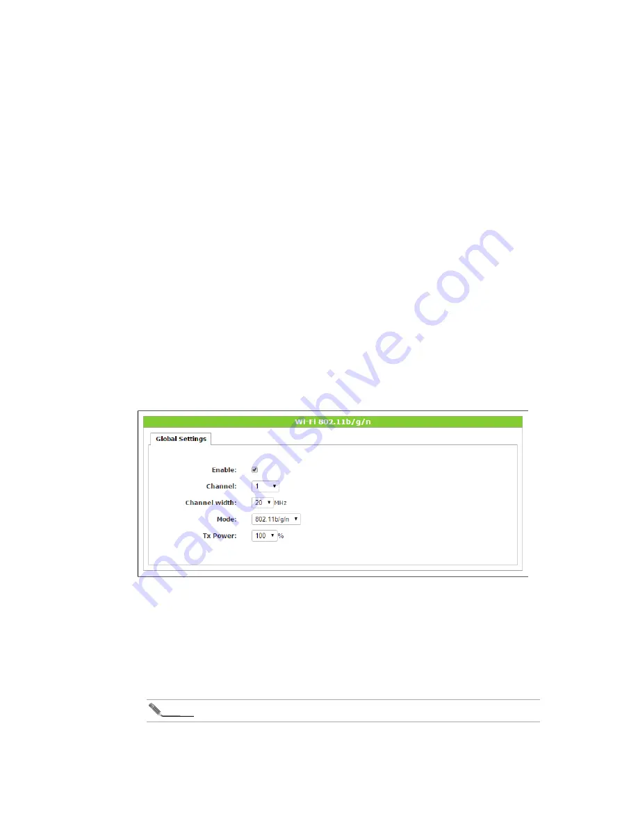
Global Wi-Fi settings

Figure 12. The global settings of the Wi-Fi tab

The Global Settings section provides you with the general Wi-Fi performance settings, common
for all 802.11b/g/n or 802.11ac interfaces. Use the following steps to configure them:

1.

Check the Enable checkbox to enable the interface, or leave it blank to disable the interface.

2.

Use the Channel drop-down list to set the channel number (or choose auto option).

3.

Use the Channel width drop-down list to set the channel width in MHz.

4.

Use the Mode drop-down list to select the available networking modes.

Note

The lists of available networking modes might vary depending on the CPE model.

5.

Use the TX power drop-down list to specify the Tx power level (in percentage).

Summary of Contents for i6800

Page 1: ...User Guide Icotera i6800 Triple play FTTH solution Published October 2016 Software version 1 10 0 Document version 2 0...

Page 2: ...ics 5 Physical Description 5 Configuring and managing the i6800 8 Web interface general overview 8 Logging in to the web interface 10 Viewing device status information 11 Managing the LAN and Wi Fi se...

Page 3: ...3 Change log Date Version Reason for a change Author 28 10 2016 2 0 First release available to public ijakobik icotera com...

Page 4: ...powerful dual core architecture where all processor intensive tasks are handled by a dedicated core leaving one core available for other immediate tasks This explicitly means that the system is still...

Page 5: ...web interface Full band CATV optional CATV filters optional USB 2 0 providing up to 500mA USB 3 0 providing up to 500mA Uplink Interface Dual speed optical uplink with auto detection Downlink Interfa...

Page 6: ...The Icotera i6800 status LEDs descriptions LED Type Type Colour State Description On Communications link established Blinking Network activity on the corresponding port Link Activity LAN port activit...

Page 7: ...e T ports two USB ports two POTS phone ports and one F type CATV RF output port Optical fiber connectors are placed inside the device Power Port The power port accepts DC 12V power source It is import...

Page 8: ...e Status menu The following figure presents the structure of the web interface Figure 3 Icotera i6800 web interface Top bar The top bar contains the Icotera logo device designation drop down list whic...

Page 9: ...selected option it can display a set of particular configuration options or a list of current i6800 status information Bottom bar In the centre of the bottom bar there are three buttons Reset resets...

Page 10: ...l be displayed Figure 5 Icotera i6800 login prompt 2 Enter your username and password in the respective fields 3 Click the Log in button to log in or use the Clear button to clear both fields and type...

Page 11: ...he device WAN interface WAN IP The IP address of device WAN interface Device name The name of the device Serial number The unit s serial number Wi Fi 802 11b g n The status of the Wi Fi 802 11b g n wi...

Page 12: ...nterface as well as the statistics of data carried through the interface Click Status WAN menu to open the WAN section Figure 7 The WAN section of the Status menu The WAN section presents basic inform...

Page 13: ...configurable options the Reset Save and Apply buttons are disabled Monitoring the LAN interface The LAN submenu of the Status main menu allows user to obtain information about the LAN interface and to...

Page 14: ...utton When the button is clicked the entry will be visible in the Static Leases section In order to manually add a static lease use the following steps 1 In the IP address field enter the IP address o...

Page 15: ...by the interface Mode The wireless mode of the wireless interface Tx Power The Tx power value for the wireless interface The Access point section contains the following information about a particular...

Page 16: ...ice Hostname The connected device s hostname Expires The lease time of the device s address Mode Mode of operation Sleep If Yes client is present but does not exchange traffic with host if No client i...

Page 17: ...i6800 17 Duration Call duration Status Call status e g answered busy Codec Codec used Dir Call direction incoming or outgoing Max Jitter Maximal jitter value in seconds Pkts lost Number of lost packe...

Page 18: ...ce will obtain their IP addresses and other necessary information automatically In order to change this setting choose from the drop down menu Static option and enter all network parameters manually 3...

Page 19: ...address should be the same It is recommended to leave Primary DNS and Secondary DNS fields at their default settings which will allow you to use your operator s DNS servers However these addresses can...

Page 20: ...the i6800 Available choices are None WEP 64 WEP 128 WPA TKIP WPA AES WPA TKIP AES WPA2 TKIP WPA AES and WPA TKIP AES Please note that None leaves the wireless AP unsecured and open for access from any...

Page 21: ...eny particular users to connect based on their Wi Fi adapters MAC address In order to configure the Access list for your interfaces complete the following steps 1 Click the Wi Fi 802 11b g n or Wi Fi...

Page 22: ...r your reference It should be set to a meaningful string that allows to identify a particular device e g my Lenovo laptop or my iPhone Mac Address physical address of the wireless adapter in your devi...

Page 23: ...nchecked you can specify custom ping parameters data size in bytes in the Packet size field and the number of packets in the Packet count field 3 Click the Ping button to send the ping packets to the...

Page 24: ...execute a site survey for all wireless networks in the neighborhood As a result of this survey a list of scanned networks will be presented In order to execute the site survey from your CPE complete t...

Page 25: ...network BSSID BSSID of the neighboring network Encryption encryption type and method used by the neighboring network Signal dBm signal quality of the neighboring network in dBm 4 In order to refresh...

Page 26: ...cking the Save button on the bottom bar or click Reset button to restore default settings After applying these settings with the Apply button the user credentials will be changed and will take effect...

Page 27: ...ible in daylight low LEDs are visible in darkness but not in daylight 3 Confirm your changes by clicking the Save button on the bottom bar or click Reset button to restore default settings After confi...

Page 28: ...steps to manage port forwarding 1 In the Services menu click the Port Forwarding submenu Figure 22 Port Forwarding section of the Services menu 2 Complete the following steps to manage port forwarding...

Page 29: ...arding click Apply button Managing DMZ Use the following steps to manage the demilitarized zone 1 In the Services menu click the DMZ submenu Figure 23 DMZ section of the Services menu 2 Check Enable c...

Page 30: ...tal control submenu Figure 25 Parental control section of the Services menu 2 Complete the following steps to manage parental control feature Check Use parental control checkbox to activate parental c...

Page 31: ...ps to use Wake On LAN feature and send magic packet to the chosen device 1 In the Services menu click the Wake On LAN submenu Figure 26 Wake On LAN section of the Services menu 2 Complete the followin...

Page 32: ...down list choose active profile Enter service URL Enter user login Enter user password Enter user domain Click Show help link to display information about special sequences which can be entered in the...

Page 33: ...ws is the responsibility of the user Without limiting the rights under copyright no part of this document may be reproduced stored in or introduced into a retrieval system or transmitted in any form o...

Reviews: