background image

10

2

DRIVER INSTALLATION

Microsoft

®

Windows

®

2000

NOTE: Driver installation with CD is required when an ad-
ditional Main unit is connected to the PC (i.e. 2 or more IC-
PCR1500 or IC-PCR2500s (same model) are connected
to the PC). In such a case, install the driver as shown
below.

q

Quit all applications when Windows is running.

w

Connect the Main unit to the desired PC’s USB port with
the supplied USB cable.

CAUTION: Icom Inc. assumes no responsibility for the
receiver’s operation resulting from the use of any other
USB cable other than the one supplied by Icom in the
original IC-PCR1500 or IC-PCR2500 package.

e

Insert the CD into the appropriate CD drive.

r

Turn the Main unit power ON.

• The power indicator lights.
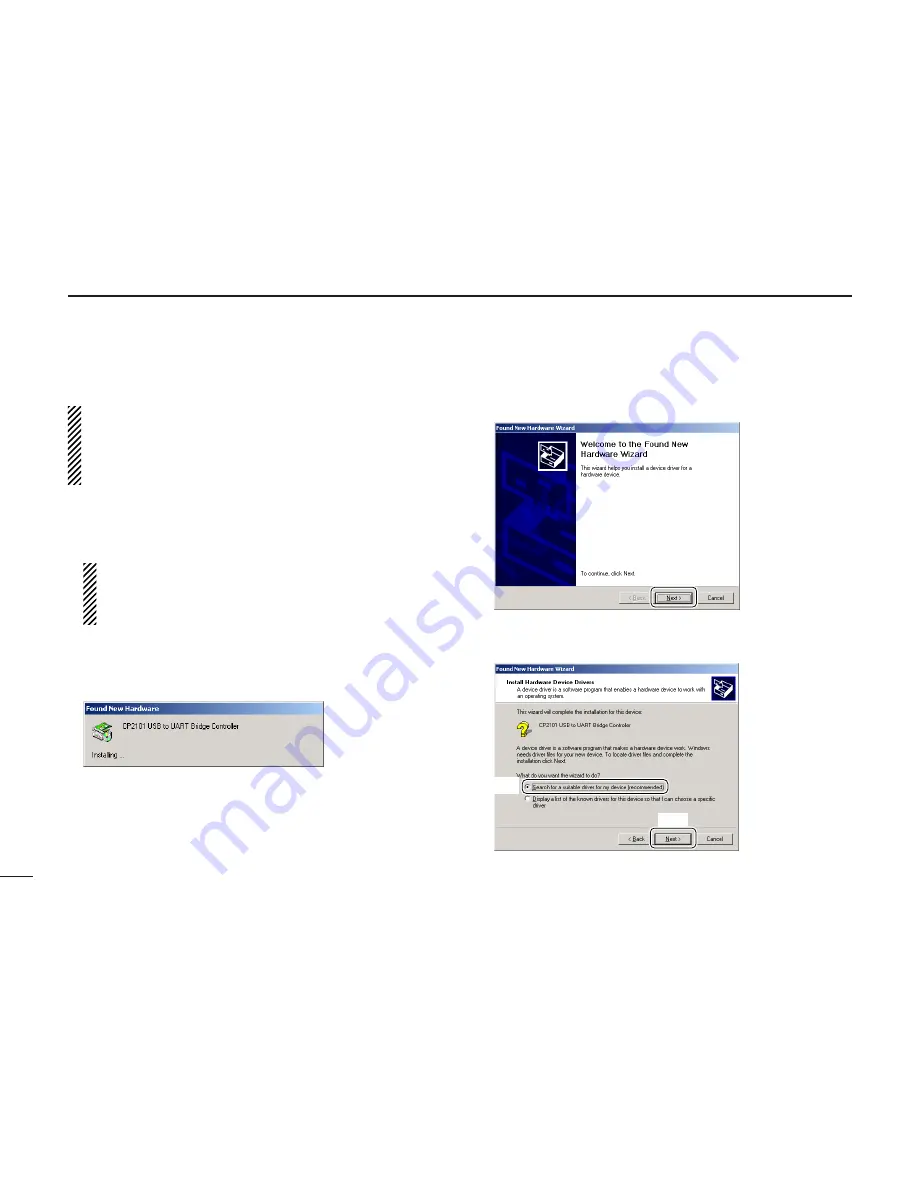
• “Found New Hardware” appears as below.

t

The CP2101 USB device is detected automatically, and the
“Found New Hardware Wizard” will come up as below.
Click [Next>].

y

Select “Search for a suitable driver for my device (recom-
mended),” then click [Next>].

Click

Select

Click

Summary of Contents for IC-PCR1500

Page 1: ...INSTRUCTION MANUAL iPCR2500 COMMUNICATIONS RECEIVER iPCR1500...

Page 2: ...TANT READ ALL INSTRUCTIONS carefully and completely before using the receiver SAVE THIS INSTRUCTION MANUAL This in struction manual contains important operating instructions for the IC PCR1500 PCR2500...

Page 3: ...onal hard disk space is required for Recording sound at high quality max 300 MB approx Storing scope data Frequency mode max 5 MB approx Time mode max 1 5 MB approx Memory channel data max 500 kB appr...

Page 4: ...re is running This may result in the computer hang up DO NOT start vehicle engine while the IC PCR1500 or IC PCR2500 control software is running when optional CP 12L is connected to a cigarette lighte...

Page 5: ...r modifications to this device not ex pressly approved by Icom Inc could void your authority to operate this device under FCC regulations This device made under license under one or more of the fol lo...

Page 6: ...ION INSTALLATION 25 29 Installation 25 Launching the IC PCR1500_2500 27 Uninstall 28 4 PANEL DESCRIPTION 30 43 Application screens on PC screen 30 Main unit 42 5 BASIC RECEIVE FUNCTIONS 44 67 Starting...

Page 7: ...ns only 80 91 Scan types 80 Programmed scan 81 Auto memory write scan 84 Memory bank scan 86 Versatile memory scan 88 Scan resume condition 90 Scan speed setting 91 8 PRIORITY SCAN Multi function rece...

Page 8: ...Digital menu indication 123 DV Digital menu 124 P25 Digital menu 125 14OPTIONAL UNIT INSTALLATION 126 128 Opening the top cover 126 UT 106 installation 126 UT 108 UT 118 installation IC PCR2500 R2500...

Page 9: ...by trying to remove the antenna holder once it has been taped into place Icom Inc cannot accept any responsibility for any damage to any item caused by the supplied tape IC PCR2500 To ground Supplied...

Page 10: ...ake sure the ground terminal of the DC power supply is grounded OPC 254L optional black white R CAUTION NEVER remove the fuse holders from the DC power cable Connects to a 12 V DC battery Pay attentio...

Page 11: ...s to the bottom of the IC PCR1500 PCR2500 as below D Cable hanger The cable hanger is convenient for fixing a cable to the wall etc Cable Clinch the hook Remove the protective paper Foot pad sheet sup...

Page 12: ...ns when Windows is running wConnect the Main unit to the desired PC s USB port with the supplied USB cable CAUTION Icom Inc assumes no responsibility for the receiver s operation resulting from the us...

Page 13: ...then select Include this location in the search click Browse uClick of the CD drive folder in My Computer The CD drive folder name e g D is depending on a PC iClick of the Driver folder in the CD driv...

Page 14: ...ts searching for the driver and shows the dialog below during search 1After the driver is found the Hardware Installation dialog box appears as below Click Continue Anyway to start the installation 2W...

Page 15: ...rial port driver Select Install from a list or specific location Advanced then click Next 5Select Search for the best driver in these locations then select Include this location in the search click Br...

Page 16: ...select Win folder Click OK 8Click Next 9The Wizard starts searching for the driver and shows the dialog below during search 0After the driver is found the Hardware Installation dialog box appears as...

Page 17: ...INSTALLATION 2 1Windows starts installing the USB driver 2After the installation is completed click Finish 3After clicking Finish the dialog appears as below 4Eject the CD Restarting the PC is recomme...

Page 18: ...e supplied USB cable CAUTION Icom Inc assumes no responsibility for the receiver s operation resulting from the use of any other USB cable other than the one supplied by Icom in the original IC PCR150...

Page 19: ...n then click Next iClick Browse oSelect the CD drive in My Computer then click Open The CD drive folder name e g D is depending on a PC 0Select the Driver folder in the CD drive then click Open Click...

Page 20: ...Win in the Driver folder then click Open 2Select Slabbus in the Win folder then click Open 3Click OK 4When the driver is found the following dialog is displayed Click Next to start the installation Cl...

Page 21: ...completed click Finish 6The Found New Hardware Wizard appears again Click Next 7Select Search for a suitable driver for my device recom mended then click Next 8Select Specify a location then click Nex...

Page 22: ...the CD drive in My Computer then click Open The CD drive folder name e g D is depending on a PC 1Select the Driver folder in the CD drive then click Open 2Select Win in the Driver folder then click O...

Page 23: ...older then click Open 4Click OK 5When the driver is found the following dialog is displayed Click Next to start the installation 6After the installation is completed click Finish 7Eject the CD Restart...

Page 24: ...er USB cable other than the one supplied by Icom in the original IC PCR1500 or IC PCR2500 package eInsert the CD into the appropriate CD drive rTurn the Main unit power ON The power indicator lights t...

Page 25: ...der in My Computer The CD drive folder name e g D is depending on a PC oSelect Win in the Driver folder click OK 0Click Next 1When the driver is found the following dialog is displayed Click Next to s...

Page 26: ...completed click Finish 3The Add New Hardware Wizard appears again Click Next 4Select Search for the best driver for your device Recom mended then click Next 5Select Specify a location click Browse Cl...

Page 27: ...der in My Computer The CD drive folder name e g D is depending on a PC 7Select Win in the Driver folder click OK 8Click Next 9When the driver is found the following dialog is displayed Click Next to s...

Page 28: ...unit to the desired PC s USB port with the supplied USB cable CAUTION Icom Inc assumes no responsibility for the receiver s operation resulting from the use of any other USB cable other than the one s...

Page 29: ...as below Select Specify the location of the driver Advanced then click Next ySelect Search for the best driver for your device Recom mended then select Specify a location click Browse uClick of the C...

Page 30: ...ect WinMe in the Driver folder click OK oClick Next 0When the driver is found the following dialog is displayed Click Next to start the installation 1After the installation is completed click Finish C...

Page 31: ...anced then click Next 3Select Search for the best driver for your device Recom mended then select Specify a location click Browse 4Click of the CD drive folder in My Computer The CD drive folder name...

Page 32: ...6Click Next 7When the driver is found the following dialog is displayed Click Next to start the installation 8After the installation is completed click Finish 9Eject the CD Restarting the PC is recom...

Page 33: ...My computer or Win dows Explorer Driver and pcr1500_2500 folders are included rDouble click Setup exe file in Pcr1500_2500 folder The InstallShield Wizard starts preparing the installation tSelect th...

Page 34: ...lation Click Browse then type the desired location if you specifying the installation location The installation starts iAfter the installation is completed click Finish oEject the CD The IC PCR1500 25...

Page 35: ...ows 98SE Me 2000 qBefore launching the program please be sure the Main unit is turned ON The power indicator lights green wClick the Start button and point to Programs ePoint to the IC PCR1500_2500 fo...

Page 36: ...tart up Windows wSelect the Control Panel in the Start menu The control panel appears as shown in the next step below eClick the Add or Remove Programs The Add or Remove Programs menu appears rClick t...

Page 37: ...APPLICATION INSTALLATION 3 yAfter the preparation Confirm Uninstall appears click OK to remove the program from the PC The uninstallation starts uAfter the uninstall is completed click Finish Click C...

Page 38: ...SETTING BUTTON p 106 Click to make the audio setting screen appear disappear uCLONE BUTTON p 132 Click to make the cloning screen appear disappear iEXIT BUTTON p 46 Click to quit the control program o...

Page 39: ...to toggle the single band operation and dualwatch op eration 4DSP DIGITAL FILTER BUTTON pgs 117 Click to make the DSP digital filter screen appear disappear 5DTMF REMOTE COMMANDER BUTTON p 104 For IC...

Page 40: ...32 4 PANEL DESCRIPTION D Receiver Multi function receiver screen 4 5 3 0 9 8 7 1 2 6 5 4 5 q 4 3 6 5 0 2 1 6 8 e w 7 6 t y u i r o 0 1 2 7 8 9 3 4 7 8 9 0 1 3b 2 3 IC PCR2500 single band operation...

Page 41: ...n Delay screen This screen is used for the settings of the scan delay details uAUDIO FREQUENCY GAIN CONTROL AF GAIN p 52 Click to adjust the audio output level Right click to increase the audio output...

Page 42: ...TTON T SCAN p 97 Click to start stop a tone scan TONE Scan blinks during scanning 1PRIORITY SCAN BUTTON PRIO p 92 Click to start stop a priority scan PRIO Scan blinks during scanning 2WEATHER ALERT BU...

Page 43: ...cted 8ATTENUATOR BUTTON ATT p 59 Click to turn the ATT Attenuator function ON or OFF ATT appears when the ATT function is turned ON 9NOISE BLANKER BUTTON NB p 60 Click to turn the NB Noise Blanker fun...

Page 44: ...is input via the 10 keypad 8 or PC keyboard 6TENKEY DECIMAL BUTTON Click to set the MHz digit when inputting a frequency via the 10 keypad 7TENKEY CLEAR BUTTON CE Click to clear the mistake while inpu...

Page 45: ...tons controls etc operate the same as the Multi function receiver screens Please refer to the explanations on pages 33 to 36 0 9 2 1 7 6 8 q w q w q w q w o i u 2 1 3b 2 1 9 0 8 3 7 4 3 4 5 0 6 5 4 e...

Page 46: ...lex DUP appears when minus duplex operation is selected t SCAN INDICATOR pgs 82 85 87 89 93 97 PROG AUTO MEMO T SCAN or PRIO appears during scanning y WEATHER INDICATOR pgs 62 63 Appears when weather...

Page 47: ...ently received frequency 5 SWEEP STEP INDICATOR p 99 Indicates band scope sweep step 6AFC INDICATOR AFC p 59 Appears when the AFC Automatic Frequency Control function is ON 7 ATTENUATOR INDICATOR ATT...

Page 48: ...he S meter squelch receive level set via the SQUELCH control 0 BUSY INDICATOR BUSY Appears when receiving a signal or when signal noise opens the squelch 1 MEMORY BANK INDICATOR p 68 Indicates the mem...

Page 49: ...omponent screen The function display indicators on the Component screen op erate the same as on the Multi function receiver screens Please refer to the explanations on pages 38 to 40 6 8 1 2 w e i t u...

Page 50: ...t Front Rear Top Power switch Speaker z x 42 4 PANEL DESCRIPTION D Rear panel Rear IC PCR2500 Rear IC PCR1500 DATA PACKET 1 USB EXT SP ANT 1 ANT 2 DC IN GND PACKET 2 q w e e r t y o i u y o i u 2 cond...

Page 51: ...ER JACK EXT SP Connects an 8 external speaker Audio output power is more than 0 5 W uCONTROLLER CONTROLLER Connects to a controller via an extension cable This con nector is only used for IC R1500 or...

Page 52: ...ol bar to select the control screen that you want to use D USB port confirmation After the software connection is turned ON step e as above the following dialog box appears at the first time Please co...

Page 53: ...45 5 BASIC RECEIVE FUNCTIONS 1 2 3 4 5 6 7 8 9 10 11 12 13 14 15 16 17 18 19 20 21 22 23 Click the zCompox icon for the Component screen IC PCR2500 IC PCR1500...

Page 54: ...ol screen Click the close button X to close the control screen Click the close button X in each TUNING PANEL MODE VOL PANEL METER SCAN PANEL and SCOPE PANEL when the Component screen is displayed Quit...

Page 55: ...LCHx zSQLx to set the squelch level Right click to increase the squelch level tight squelch Left click to decrease the squelch level loose squelch When clicking and holding zSQUELCHx zSQLx the squelch...

Page 56: ...ency range the previously selected frequency is automatically selected after clicking Enter D Using the tuning dial Click zDIALx to set the receive frequency with the selected tuning step Right click...

Page 57: ...ive band only Active band only MAIN SUB 10 KEYPAD 10 KEYPAD 10 KEYPAD 10 KEYPAD 10 KEYPAD 10 KEYPAD zCEx z x zENTx zDIALx zCEx z x zENTx zDIALx zDIALx Compo screen Receiver screen IC PCR2500 IC PCR150...

Page 58: ...200 kHz 500 kHz 1 MHz 10 MHz USER When USER is selected the user programmed tuning step de fault 5 kHz in User TS screen is selected p 51 D Tuning step selection Using Receiver Compo screen Right clic...

Page 59: ...ht click zYx TS or zZx TS or click zTSx indication to display a tuning step list then select USER TS Setting You can edit the desired tuning step from 0 001 9999 999 kHz in 0 001 step directly Availab...

Page 60: ...PC s UP or DOWN key also sets the audio level Using Simple screen Click zAFx to set the audio level Right click to increase the audio level Left click to decrease the audio level When clicking and hol...

Page 61: ...the squelch level Right click to increase the squelch level tight squelch Left click to decrease the squelch level loose squelch When clicking and holding zSQUELCHx the squelch level scrolls up or do...

Page 62: ...and short wave broadcasts WFM is used for FM broadcast stations 76 107 9 MHz When using zAUTO Mx automatic mode a receive mode IF filter passband width tuning step etc are selected automatically after...

Page 63: ...t eClick a cell in the Freq Low column and the desired line rInput the lower frequency of the frequency range from the keyboard then push Enter When nothing is input into the Freq Low or Freq High col...

Page 64: ...button lights green when Simple screen is displayed Mute function This function is used to mute the received audio signal Click zMUTEx to temporarily mute audio output MUTE appears when Receiver Compo...

Page 65: ...frequency p 48 wRight click zDUPx to display the DUP Offset screen eSet the desired offset frequency within 0 000000 1000 000000 MHz range then click the close button X to close the setting screen rLe...

Page 66: ...kHz 15 kHz or 50 kHz WFM mode 50 kHz or 230 kHz FM mode 6 kHz 15 kHz or 50 kHz Using Receiver Compo screen Click zWIDEx or zNARx to select the desired IF filter widths Using Simple screen Click zFILTE...

Page 67: ...m broadcast stations pocket beep ers nearby amateur radio stations etc can cause distortion of receive signals The attenuator function can reduce signal strength of interfering signals by approximatel...

Page 68: ...ontrols receiver gain to produce a constant audio output level even when the received signal strength is varied by fading etc The AGC fast is always selected in FM or WFM mode Click z zAGCx x z zAGC F...

Page 69: ...ency passband frequency to reject in terference It activates in SSB CW modes only Using Receiver Compo screen qAdjust the zSHIFTx control for a minimum interference sig nal level The audio tone may be...

Page 70: ...to close the WX Alert screen r Click the zWXx button to turn the weather alert function ON t When the alert is detected a beep sounds and the indica tion will be displayed as at right y Click the zWX...

Page 71: ...screen if it is not displayed w Click the zOthersx tab to display the squelch delay setting e Click the zShortx or zLongx radio button to set the squelch delay rClick the close button X to close the S...

Page 72: ...band operation only Main band is activate and Sub band is inhibited The single band operation s control screens are similar as the IC PCR1500 q Click the zSinglex icon on the tool bar to toggle the s...

Page 73: ...65 5 BASIC RECEIVE FUNCTIONS 1 2 3 4 5 6 7 8 9 10 11 12 13 14 15 16 17 18 19 20 21 22 23 Single band operation Dualwatch operation Compo screen Single band operation Dualwatch operation Simple screen...

Page 74: ...zSinglex icon on the tool bar to select the single band operation if the dualwatch operation is selected Even when turns the single band operation from Sub band fre quency operation the Main band fre...

Page 75: ...an be set to active band only depending on the control screen Then you must select the desired band Main band or sub band to active band Click the zMAINx or zSUBx icon on the tool bar to toggle the ac...

Page 76: ...tenuator ON OFF p 59 Tuning step p 50 Select memory scan setting p 88 Memory skip scan setting p 88 Squelch control system ON OFF and its frequency or code p 79 120 122 Remark memory channel comment p...

Page 77: ...he zMemory Editx icon on the tool bar to call up the Memory Channel Editor screen if it is not displayed w Click zYx BANK or zZx BANK to select a memory bank e Select the desired memory channel r Clic...

Page 78: ...NK or zZx BANK to select a memory bank to be programmed w Click zYx MEMO or zZx MEMO or use the 10 keypad to input the desired memory channel number then click zMchx to select a memory channel to be p...

Page 79: ...contents can be initialized using the preset_e mch file which is saved in mch format q Click the zMemory Editx icon on the tool bar to call up the Memory Channel Editor screen if it is not displayed...

Page 80: ...an be made except for the name r Double click the desired cell directory or right click the cell then click Edit Enter from the displayed menu to set other items such as duplex direction mode tuning s...

Page 81: ...r the memory name of the control software Sub Name up to 6 characters is used for the memory name of the IC R1500 or IC R2500 controller r Edit the desired memory name from the PC keyboard then push E...

Page 82: ...nnel Editor screen if it is not displayed w Click zYx BANK or zZx BANK to select the desired memory bank e Right click any cell of the desired memory channel to be copied then select Copy Ctrl C from...

Page 83: ...y Editx icon on the tool bar to call up the Memory Channel Editor screen if it is not displayed w Click zYx BANK or zZx BANK to select a memory bank e Right click a cell on the desired channel that yo...

Page 84: ...creen contents changes to the selected bank s r After selection click close button X to close the mem ory channel list screen Memory channel clearing D Clearing from the receiver screen q Click zYx BA...

Page 85: ...ell of the unneeded memory channel to be cleared then click Clear from the displayed menu r Click OK in the displayed dialog box to clear the selected memory channel contents Memory Edit w Click e Cli...

Page 86: ...y channel data in the PC can be loaded Click Open in the File menu then select the desired memory channel data file that is saved previously Creating new memory channel data file The new memory channe...

Page 87: ...the CSV file is saved then click Open rSelect the desired CSV file that you want to import then click Open The selected CSV file is imported Exporting a CSV file The selected bank contents are export...

Page 88: ...ch 50 ch 1 ch 2 ch 3 ch 4 ch 5 ch 6 ch 49 Not yet programmed ch 50 ch 1 ch 2 ch 3 ch 4 ch 5 ch 6 ch 49 Skips unwanted memory channels that inconvenient ly stop scanning This func tion can be turned O...

Page 89: ...High or at tenuator if desired Program the start frequency first otherwise no setting can be done except for the name rEnter the desired scan edge channel number then click the close X button to clos...

Page 90: ...k the close X button to close the setting screen D Starting a programmed scan qMake sure the squelch is set to the threshold point closed condition wRight click the zPROGx button to call up the Progra...

Page 91: ...R1500 IC PCR2500 Appears Appears Blinks Blinks Blinks tClick the zPROGx button to start programmed scan PROG Scan blinks and PROG appears while scanning yTo stop the scan click zSTOPx or zPROGx When t...

Page 92: ...UTOx to call up the Auto MW Scan setting screen if it is not displayed eEnter the programmed scan range number to be scanned in Program No rSelect a memory bank to be written then click the close X bu...

Page 93: ...creen Receiver screen IC PCR2500 IC PCR1500 IC PCR2500 IC PCR1500 zSTOPx zAUTOx zAUTOx zPAUSEx zPAUSEx zSTOPx Appears IC PCR1500 IC PCR2500 Appears Appears Blinks Blinks Blinks tClick zAUTOx to start...

Page 94: ...creen if it is not displayed rSelect the bank scan condition from Current Bank Select Bank or All Bank a Current Bank Scans memory channels within the current bank b Select Bank Scans memory channels...

Page 95: ...reen Receiver screen IC PCR2500 IC PCR1500 IC PCR2500 IC PCR1500 zSTOPx zMEMOx zMEMOx zPAUSEx zPAUSEx zSTOPx Appears IC PCR1500 IC PCR2500 Appears Appears Blinks Blinks Blinks y Click the zMEMOx butto...

Page 96: ...he SEL box select memory scan repeatedly scans memory channels these SEL settings are turned ON in memory channel list screen When selecting the SKIP box memory skip scan repeatedly scans memory chann...

Page 97: ...STOPx Appears IC PCR1500 IC PCR2500 Appears Appears Blinks Blinks Blinks eClick the zMEMOx button to start the desired memory scan MEMO Scan blinks and MEMO appears while scanning rTo stop the scan cl...

Page 98: ...disappears b Delay Volume When setting a delay time using the DELAY control on Receiver screen or Component screen scan pauses when receiving a signal and then resumes after the specified delay c Scan...

Page 99: ...e zSPEEDx control to set the speed at which scans search through frequencies memories for signals Right click to increase the speed level Left click to decrease the speed level When clicking and holdi...

Page 100: ...zPRIOx button to call up the Priority Scan setting screen if it is not displayed METER SCAN Active band only MAIN SUB Compo screen Receiver screen IC PCR2500 IC PCR1500 IC PCR2500 IC PCR1500 zPRIOx zP...

Page 101: ...o 60 sec in Priority Inter val then click the close X button to close the setting screen Click zCHECKx to start priority scan t Click zPRIOx button to start priority scan PRIO Scan blinks and PRIO app...

Page 102: ...uWhen the received signal includes a matched tone squelch opens and the signal can be heard When the Reverse Action check box is checked in step t the received audio signal is muted When the received...

Page 103: ...muted When the received signal s code does not match tone squelch does not open however the S indicator shows signal strength iClick zDTCSx again to cancel the DTCS squelch DTCS disappears Available...

Page 104: ...DTCS setting screen Pocket beep operation This function uses subaudible tones for calling and can be used as a common pager to inform you that someone has called while you were away from the receiver...

Page 105: ...lch opens and the tone frequency is temporarily programmed into the selected memory chan nel The tone scan pauses when a TSQL tone frequency or 3 digit DTCS code is detected The decoded TSQL tone freq...

Page 106: ...ency When a strong signal is received the waveform is indicated small eClick zSPAN x or zSPAN x to select the sweep width through SPAN1 25 0 kHz to SPAN5 500 kHz Choose SPAN1 when band conditions are...

Page 107: ...ation Compo screen Receiver screen Frequency Time Frequency Time Center frequency LIMIT indicator Sweep step indicator Center frequency LIMIT indicator Sweep step indicator Time interval Time interval...

Page 108: ...parated Values file format qClick the sweep start button z x to begin a sweep p 98 Frequency mode is selected when zFREQx is clicked and Time mode is selected when zTIMEx is clicked wClick the recordi...

Page 109: ...nd only Compo screen Receiver screen IC PCR2500 IC PCR1500 IC PCR2500 IC PCR1500 zTIMEx zTIMEx zSTOPx zSTOPx zSTARTx zSTARTx zRECx zRECx zTIMEx Right click Click Click When Time mode is selected q Sel...

Page 110: ...e FREQ setting screen if it is not displayed wClick the desired frequency step range in the Automatic Sweep Step Limit The sweep step range can be selected from one of 1 100 kHz 1 50 kHz or 1 25 kHz e...

Page 111: ...The following optional functions are available for the band scope function These settings can be defined using the Scope FREQ screen WFM Monitor function The band scope function is normally used in A...

Page 112: ...x icon on the tool bar to call up the DTMF Remote Commander screen if it is not displayed eClick zON OFFx on the DTMF Remote Commander screen to toggle the DTMF decoder circuit ON and OFF The indicato...

Page 113: ...Message Action Execute File or Play WAV File when the received code is matched to the Receive CODE setting a Display Message To display a entered message in the text box b Action Execute File To exec...

Page 114: ...500 can be adjusted the AF gain level for Main band or Sub band independently rCheck the Mute check box to turn the mute function ON or OFF When this function is turned ON the received audio signal is...

Page 115: ...displayed as at left wCheck the Confirmation Beep check box to turn the con firmation beep emission ON eEnter the wave file name in the Pocket Beep text box di rectly or click to select the desired w...

Page 116: ...onnect the Main unit then turn the Main unit s power OFF The power indicator of the Main unit goes out Microsoft Windows XP wClick the Start button and click Control Panel in My computer eClick Sounds...

Page 117: ...Control Panel in Settings eDouble click on Multimedia then click the Audio tab rConfirm the Preferred device in Sound Playback Making a note is recommended tClick close button X to close the Sounds an...

Page 118: ...items eClick the close button X to close the Multi CH Monitor list screen The channel name and frequency are displayed on the pro grammed channel rClick the close button X to close the Multi CH Monito...

Page 119: ...While scanning the receive audio is muted SCANNING blinks in the information box The zSTARTx button changes to the zSTOPx button while scan ning The background color changes according to the receivin...

Page 120: ...ed folder in which the record ing data is saved After the folder selection click OK tClick the recording start button z x to start recording the receiving signal IC PCR2500 can record the receiving si...

Page 121: ...rding data You can play back the recorded signal with the installed media player e g Windows Media Player etc in the PC Please refer to the media player s instruction manual for de tails Recording scr...

Page 122: ...ze becomes larger q Receive a signal p 47 w Click zRecordingx icon on the tool bar to call up the Recording screen if it is not displayed e Click zSettingx to display the setting menu r Click Z in Sam...

Page 123: ...l p 47 w Click the zRecordingx icon on the tool bar to call up the Recording screen if it is not displayed e Click zSettingx to display the setting menu r Click the Rec Remote check box to turn the re...

Page 124: ...Key Ctrl Shift and Alt keys act as shortcut keys with another key combination Some keys cannot be set as shortcut key y Click Add to add the shortcut key or combination of keys to the list uClick clos...

Page 125: ...picks out desired signals which are buried in noise The received AF signals are converted to digital signals and then the desired signals are separated from the noise This function is available for a...

Page 126: ...l installa tion is not necessary Click the zMAINx icon on the tool bar to select the Main band Using Receiver Compo screen Click zDVx or zP25x to select the desired digital mode Using Simple screen Cl...

Page 127: ...icon on the tool bar to call up the Set ting screen if it is not displayed w Click the zDVx tab to display the DV setting e Click q Click Setting screen Check the check box to turn the stanby beep em...

Page 128: ...ed appears in the function display uClick the close button X to close the DV Digital SQL setting screen iWhen the received signal includes a matched call sign or code squelch opens and the signal can...

Page 129: ...ome versions are already installed UT 122 q Click the zSettingx icon on the tool bar to call up the Set ting screen if it is not displayed w Click the zP25x tab to display the P25 setting e Click q Cl...

Page 130: ...vailable for NAC yCheck the Pocket Beep check box to turn the pocket beep function ON if desired appears in the function display uClick the close button X to close the P25 Digital SQL setting screen i...

Page 131: ...dicates that the each screen is displayed P25 Record call record screen DV Terminal Window screen DV Message screen DV Received call record screen P25 Record call record screen P25 Digital SQL screen...

Page 132: ...age D DV Terminal window DV Terminal Window screen DV Message screen Check the check box to turn the DV message screen automatically when new message is received DV Received call record screen Check t...

Page 133: ...8 19 20 21 22 23 P25 Digital menu D P25 Received call record D P25 ID List P25 ID List screen P25 Received call record screen Check the check box to turn the DV Received call record screen automatical...

Page 134: ...careful not to lose the screws eAfter installing the optional unit or any internal setting is fin ished replace the top cover cables and screws to the orig inal position UT 106 installation The optio...

Page 135: ...the LOGIC board Be sure not upside down yRemove the protective paper from the supplied velcro then attach it to the UT 106 and the shield case of MAIN board uReplace the top cover cables and screws t...

Page 136: ...26 wConnect the UT 108 or UT 118 as shown below eReplace the top cover cables and screws to the original position UT 122 installation IC PCR2500 R2500 only qRemove the top cover as shown in p 126 wCon...

Page 137: ...cover as shown in p 126 wToggle the switch as desired shown at right Toggles the switch to SPEAKER when an external speaker is connected to the receiver default Toggles the switch to PHONES when head...

Page 138: ...mber of the Main unit are displayed During the control software is connected to Main unit USB port selection in inhibited w Confirm the connected USB port and serial number click zOKx D USB port selec...

Page 139: ...unction pgs 106 112 are dis abled but the computer running speed will be faster than when the USB audio output function is ON qClick zPowerx icon on the tool bar to disconnect the Main unit w Click zP...

Page 140: ...med contents from a personal computer to a re ceiver using the IC PCR1500 PCR2500 program See the cloning instruction manual supplied with the IC R1500 or IC R2500 for details Click Clone icon on the...

Page 141: ...The squelch is open The start and end frequencies are the same The squelch is open Only 1 memory channel is programmed or other channels are set as skip channel The computer does not recognize the co...

Page 142: ...Main unit 2600 Controller R1500 R2500 1100 incl 100 scan edges Frequency resolution 1 Hz 10 Hz 20 Hz 50 Hz 100 Hz 500 Hz 1 kHz 2 5 kHz 5 kHz 6 25 kHz 8 33 kHz 9 kHz 10 kHz 12 5 kHz 15 kHz 20 kHz 25 k...

Page 143: ...an 18 V WFM 1 kHz 52 5 kHz Dev 12 dB SINAD 50 000 699 999 MHz Less than 1 4 V 700 000 1300 000 MHz Less than 1 8 V 1300 000001 2299 999 MHz Less than 18 V 2300 000 3000 000 MHz Less than 56 V AM 1 kHz...

Page 144: ...FM More than 230 kHz 6 dB typical AF output power at 12 0 V DC More than 0 5 W at 10 distortion with an 8 load Ext speaker connector 2 conductor 3 5 d mm 1 8 8 Packet connector 2 conductor 3 5 d mm 1...

Page 145: ...e Essential Test Suite measurements have been performed Kind of equipment COMMUNICATIONS RECEIVER Type designation iPCR1500 R1500 Version where applicable This compliance is based on conformity with t...

Page 146: ...ments have been performed Kind of equipment COMMUNICATIONS RECEIVER Type designation iPCR2500 R2500 Version where applicable This compliance is based on conformity with the following harmonised standa...

Page 147: ...139 MEMO...

Page 148: ...POR DEN GBR BEL ITA FIN IRL LUX GRE SUI NOR Intended Country of Use GER FRA ESP SWE AUT NED POR DEN GBR BEL ITA FIN IRL LUX GRE SUI NOR IC PCR1500 22 Europe IC PCR2500 22 Europe IC PCR1500 23 U K IC P...

Reviews: