2001 NEW
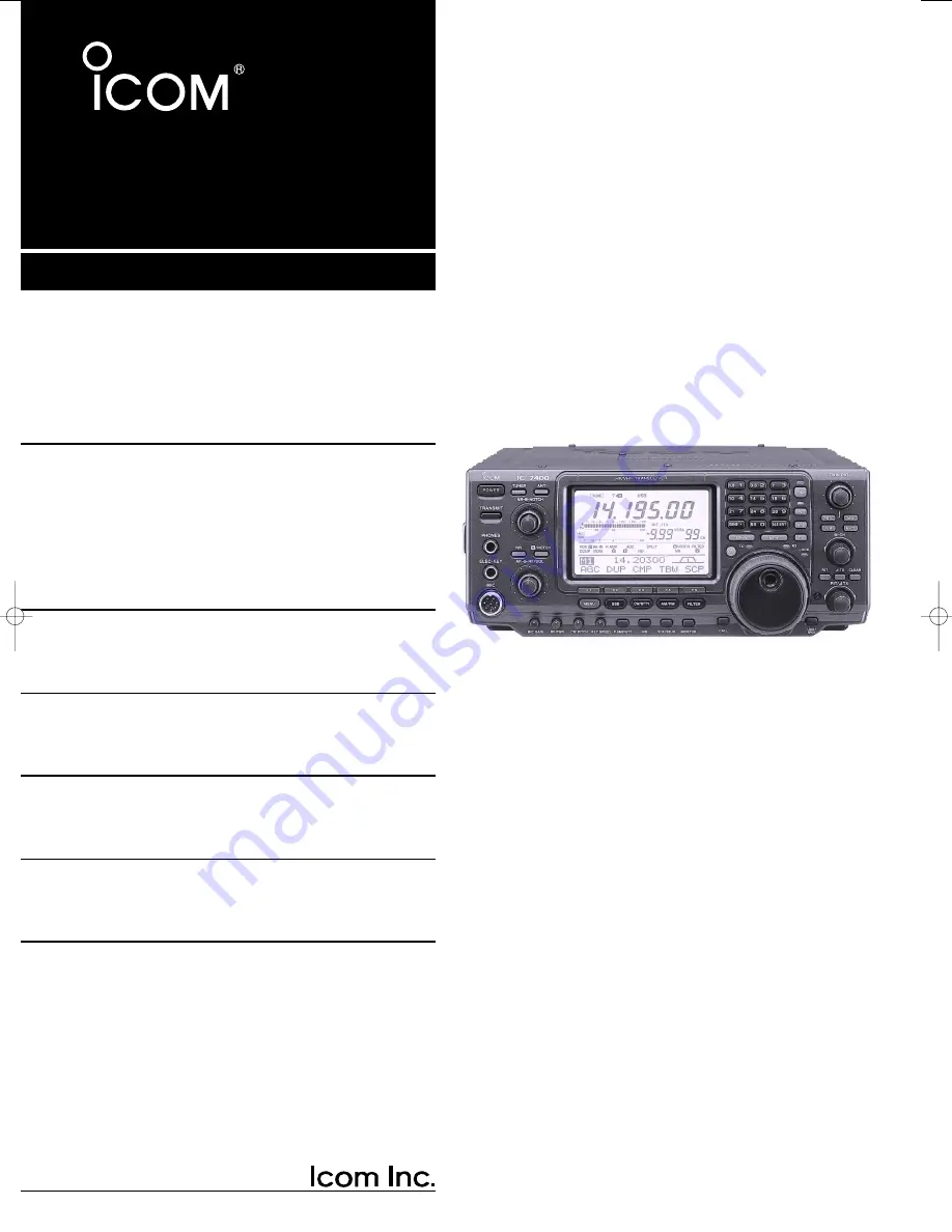
HF/VHF ALL MODE TRANSCEIVER
i7400
INSTRUCTION MANUAL
IC-7400.qxd 02.4.2 11:34 Page 1
Page 1: ...HF VHF ALL MODE TRANSCEIVER i7400 INSTRUCTION MANUAL ...
Page 2: ...now or any liquids AVOID using or placing the transceiver in areas with tem peratures below 10 C 14 F or above 60 C 140 F Be aware that temperatures on a vehicle s dashboard can exceed 80 C 176 F resulting in permanent damage to the transceiver if left there for extended periods AVOID placing the transceiver in excessively dusty envi ronments or in direct sunlight AVOID placing the transceiver aga...
Page 3: ... hold function 50 Twin PBT operation 51 Noise reduction 52 Notch function 52 Dial lock function 52 Voice squelch control function 53 6 FUNCTIONS FOR TRANSMIT 54 60 VOX function 54 Break in function 55 TX function 56 Monitor function 56 Speech compressor 57 Transmit filter width selection 57 Split frequency operation 58 Quick split function 59 Measuring SWR 60 7 MEMORY OPERATION 61 67 Memory channe...
Page 4: ...s RWARNING NEVER ground station equip ment or antennas to house gas lines NEVER at tach ground lines to plastic pvc pipe D D Some Symptoms if inadequate grounding a Poor DC Ground 50 60 Hz hum on the audio either Rx or Tx without the antenna connected If you feel a tingling sensation when you touch a metal surface Surfaces such as the cover of your radio or power supply b Poor RF Ground While tran...
Page 5: ... 30 mm 9 8 in 10 mm 3 8 in 1 2 mm 1 16 in R WARNING Although a mag mount antenna works great on a vehicle DO NOT use the IC 7400 with this type of antenna CAUTION Although your IC 7400 has protection to drop down power with a high SWR this does not completely protect the transceiver from transmis sion without an antenna Make sure you have an antenna connected whenever you transmit with your radio ...
Page 6: ...r IC 7400 a Iambic Key paddle Use a 6 35 d mm 1 4 stereo plug and connect to the ELEC KEY jack located on the front of the radio b Straight Key Use a 6 35 d mm 1 4 mono plug and connect key to the back of the radio c External Keyer Use a 6 35 d mm 1 4 mono plug and connect to the back of the radio d Computer Keying Use a 6 35 d mm 1 4 mono plug and connect to the back of the radio NOTE You will ne...
Page 7: ... clockwise MIC GAIN The mic gain fully counter clock wise RF SQL The control for the RF Gain and Squelch circuits 12 o clock CW PITCH The control for the CW pitch 12 o clock KEY SPEED Internal CW Keyer Speed fully counter clockwise NOTCH Control for the manual notch 12 o clock 2 Resetting the CPU Although you have purchased a brand new radio some settings may be changed from the factory defaults d...
Page 8: ... you want to oper ate You will notice the tuning speed TS is 10 Hz res olution Page 22 will instruct you on how to set the tuning speed TS for 1 Hz resolution NOTE Although you can directly enter the fre quency with the keypad using the Band Stacking Register and the tuning knob is the most popular method of hoping around the bands For more in formation regarding the direct frequency entry method ...
Page 9: ...nce the NR control will determine how much the noise can be effectively reduced Turning the control too far clockwise may cause some distortion to occur on the received signal The NR control should only be turned as far clockwise as is necessary Use this control along with RF gain NB noise blanker if needed and IF filters as well to minimize the effects of noise on the target signal Noise reductio...
Page 10: ...ile also taking this in terference out of the AGC Bottom line this will ei ther eliminate or greatly reduce the pumping of the AGC from the interfering signal AGC DUP CMP TBW SCP A NOTCH NOTCH Notch function indicators NR NOTCH Low frequency High frequency Hint The Automatic Notch will not operate in the SSB data CW or RTTY modes d Filters Your IC 7400 has an incredible IF DSP based filter network...
Page 11: ... row both filters thus the filter shape is not nar rowed You may hear some signal artifacts pass through this filter adjustment PBT operation example BW Filter set mode indication Shows the selected filter and passband width BW Indication while PBT setting Appears when passband is shifted By pushing PBTC for 1 sec the shifted value returns to the default setting and the dot disappears AGC DUP CMP ...
Page 12: ...dB in 1 dB steps RX Treble SSB O 4 We hope these pointers have been helpful Now you are ready for the Ready to call CQ Ready to call CQ The 32 bit DSP in your IC 7400 is capable of allowing you to selects transmit audio for phone modes POWER TRANSMIT PHONES ELEC KEY MIC NR A NOTCH TUNER ANT HF VHF TRANSCEIVER NR NOTCH AF MIC GAIN RF PWR CW PITCH F 1 F 2 F 3 F 4 F 5 XFC MP W GENE 50 0 21 7 24 8 28 ...
Page 13: ...s equipped with a very powerful equalizer sys tem with 121 possible combinations This is achieved by using the separate bass and treble adjustments The default for both the Base and Treble is at 0 dB Entering Microphone Tone Control set mode q Push MENU several times or until M2 is shown on the display w Push F4 TCN for the Tone Control set mode e Push the appropriate mode switch to adjust SSB AM ...
Page 14: ... appropriate microphones See p 12 for microphone connector information y RF GAIN CONTROL SQUELCH CONTROL RF SQL outer control Adjusts the RF gain and squelch threshold level The squelch removes noise output from the speaker closed condition when no signal is received The squelch is particularly effective for FM It is also available for other modes 12 to 1 o clock position is recommended for any se...
Page 15: ... can be set 2 AUTO NOTCH MANUAL NOTCH SWITCH A NOTCH p 52 Toggles the notch function between manual and au tomatic when pushed NOTCH appears when manual A NOTCH appears when automatic notch is selected 3 NOTCH CONTROL NOTCH outer control p 52 Adjusts the notch filter frequency to remove an in terfering signal 4 ANTENNA SELECTOR SWITCH ANT p 74 Switches the antenna connector selection between ANT1 ...
Page 16: ...tes high gain preamp for 24 MHz band and above Push for 1 sec to toggle the attenuator function ON and OFF What is the preamp The preamp amplifies received signals in the front end cir cuit to improve the S N ratio and sensitivity Select P AMP1 or P AMP2 when receiving weak signals What is the attenuator The attenuator prevents a desired signal from distorting when very strong signals are near the...
Page 17: ...kHz in 10 Hz steps 0 RIT SWITCH RIT p 47 Turns the RIT function ON and OFF when pushed Use the RIT TX control to vary the RIT frequency Adds the RIT shift frequency to the operating fre quency when pushed for 1 sec What is the RIT function The RIT Receiver Incremental Tuning shifts the receive fre quency without shifting the transmit frequency This is useful for fine tuning stations calling you on...
Page 18: ...RX Lights green while receiving a signal and when the squelch is open 3 LOCK INDICATOR LOCK p 52 Lights when the dial lock function is activated 4 QUICK TUNING SWITCH TS p 21 Turns the quick tuning step ON and OFF While the quick tuning indicator is displayed the fre quency can be changed in programmed kHz steps 0 1 1 5 9 10 12 5 20 and 25 kHz quick tuning steps are available While the quick tunin...
Page 19: ...PBT control General PBT function electronically narrows the IF passband width to reject interference This transceiver uses the DSP circuit for the PBT function 8 SPLIT INDICATOR p 58 Lights during split operation 9 FREQUENCY INPUT SWITCH F INP p 22 Push to toggle keypad input between frequency and band The frequency input indicator lights when fre quency input is selected for the keypad 0 FREQUENC...
Page 20: ... control level 16 V DC 0 5 A CAUTION Be sure the linear amplifiers keying cir cuit control voltage is compatible to the IC 746PRO before connecting to SEND o ALC INPUT JACK ALC p 17 Connects to the ALC output jack of a non Icom lin ear amplifier 0 ACCESSORY SOCKET 2 ACC 2 1 ACCESSORY SOCKET 1 ACC 1 Enables connection of external equipment such as a linear amplifier an automatic antenna selector tu...
Page 21: ...Connected in parallel with ACC 2 pin 5 ACC 2 PIN No NAME DESCRIPTION SPECIFICATIONS 1 2 3 4 5 6 7 1 8 V Regulated 8 V output Output voltage 8 V 0 3 V Output current Less than 10 mA 2 GND Same as ACC 1 pin 2 3 HSEND Same as ACC 1 pin 3 4 BAND Band voltage output Output voltage 0 to 8 0 V Varies with amateur band 5 ALC Same as ACC 1 pin 8 Input output pin 144 MHz only Ground level 0 5 V to 0 8 V 6 V...
Page 22: ...EL INDICATOR p 71 Appears when the selected memory channel is set as a select memory channel o BLANK MEMORY INDICATOR p 61 Appears when the selected memory channel is blank 0 1 4 TUNING DIAL SPEED INDICATOR p 21 Appears when the tuning dial speed is set so that one rotation is equal to 1 4 of the normal rotation 1 VOICE SQUELCH CONTROL INDICATOR p 53 Appears during VSC Voice Squelch Control func t...
Page 23: ...tivated 1 DTCS INDICATOR p 43 Appears during DTCS operation 2 TONE SQUELCH INDICATORS T appears when the repeater tone is activated p 44 TSQL appears during tone squelch operation p 42 3 DUPLEX INDICATOR p 44 DUP or DUP appears during repeater opera tion 4 NOISE REDUCTION INDICATOR p 52 Appears when the noise reduction is activated 5 NOTCH INDICATORS p 52 NOTCH appears when the manual notch func t...
Page 24: ...DTH p 57 Push to select the transmission bandwidth Bandwidth is selectable from narrow middle and wide MEMORY KEYER MENU p 29 Push to select the memory keyer or keyer send menu depending on the KEYER 1st Menu setting in the set mode p 86 RTTY MENU p 36 Push to select the RTTY menu BAND SCOPE FUNCTION p 46 Push to select the band scope screen D DM2 FUNCTIONS SCAN MENU p 69 Push to select the scan m...
Page 25: ...ION DO NOT short pin 2 to ground as this can damage the internal 8 V regulator NOTE DC voltage is applied to pin 1 for micro phone operation Take care when using a non Icom microphone y GND PTT ground t PTT r Main readout squelch switch q Microphone input w 8 V DC output e Frequency up down u GND Microphone ground i Main readout AF output varies with AF BAL q w MIC FUNCTION DESCRIPTION Pin No w 8 ...
Page 26: ...sion or electric shock Antenna connection For radio communications the antenna is of critical im portance along with output power and sensitivity Se lect antenna s such as a well matched 50 Ω antenna and feedline 1 5 1 or better of Voltage Standing Wave Ratio VSWR is recommended for your desired band Of course the transmission line should be a coaxial cable When using 1 antenna use the ANT1 connec...
Page 27: ...RANSMIT PHONES ELEC KEY MIC TUNER ANT NR NOTCH AF RF SQL NR A NOTCH CW KEY MICROPHONES p 100 A straight key can be used when the internal electronic keyer is turned OFF in keyer set mode p 34 HM 36 SM 20 optional dot com dash GROUND p 13 Use the heaviest gauge wire or strap available and make the connection as short as possible Grounding prevents electrical shocks TVI and other problems ANTENNA 1 ...
Page 28: ...PLIT PBTC F INP A B V M MW M CL KEY SPEED P AMP ATT NB VOX BK IN MONITOR CALL LOCK SPCH RF SQL i7400 MENU SSB CW RTTY AM FM FILTER HEADPHONES MIC The AFSK modulation signal can be input from MIC p 77 AH 2b AH 4 p 76 ANTENNA 1 2 p 17 Connects a linear amplifier antenna selector etc SEND ALC p 17 Used for connecting a non Icom linear ampli fier When using the AH 4 it must be connected to the ANT1 co...
Page 29: ...ower supply 13 8 V at least 23 A Black _ Red to DC power socket to ground terminal Supplied DC power cable OPC 639 12 V battery Supplied DC power cable red _ black Crimp Solder Grommet NEVER connect to a 24 V battery NOTE Use terminals for the cable connections NEVER connect to a battery without supplied DC fuses otherwise a fire hazard may occur PS 125 Connect to an AC outlet using the supplied A...
Page 30: ...e or ruin the linear amplifier The specifications for the SEND relay are 16 V DC 0 5 A If this level is exceeded a large external relay must be used External antenna tuner connection CONNECTING THE AH 4 The AH 4 must be connected to ANT1 To an antenna ACC 1 ANT ANT1 ACC 2 INPUT1 REMOTE EXCITER 1 1 2 GND GND IC PW1 AC outlet Non European versions 100 120 220 240 V European version 230 V Ground Tran...
Page 31: ...S all programmed contents in memory channels and returns programmed values in set mode to default values 3 18 BASIC OPERATION When first applying power CPU resetting Initial settings After resetting the transceiver set controls and switches as shown in the figure below CW Clockwise CCW Counterclockwise POWER TRANSMIT PHONES ELEC KEY MIC NR A NOTCH TUNER ANT HF VHF TRANSCEIVER NR NOTCH AF MIC GAIN ...
Page 32: ...ng register When a fourth frequency and operating mode are se lected on a band the first register set in step q is over written Band keys BAND REGISTER 1 REGISTER 2 REGISTER 3 1 8 MHz 1 900000 MHz CW 1 910000 MHz CW 1 915000 MHz CW 3 5 MHz 3 550000 MHz LSB 3 560000 MHz LSB 3 580000 MHz LSB 7 MHz 7 050000 MHz LSB 7 060000 MHz LSB 7 020000 MHz CW 10 MHz 10 120000 MHz CW 10 130000 MHz CW 10 140000 MH...
Page 33: ...ode for your operation D DSelecting the VFO A B Push A B to switch between the VFO A and VFO B VFO A or VFO B appears D DVFO equalization Push A B for 1 sec to equalize the undisplayed VFO condition to the displayed VFO 3 beeps sound when the VFO equalization is completed CONVENIENT Use two VFOs as a quick memory When you find a new station but you wish to continue searching the Two VFO system can...
Page 34: ...function appears e Push TS for 1 sec to enter the tuning step set mode r Rotate the tuning dial to select the desired tuning step t Push TS to exit the tuning step set mode D D1 4 Tuning step function SSB data CW and RTTY only While operating in SSB data CW RTTY the 1 4 function is available for critical tuning Dial rotation is reduced to 1 4 of normal when the 1 4 function is in use While M1 is s...
Page 35: ...set mode if de sired p 81 D DFrequency setting with the keypad The transceiver has a keypad for direct frequency entry as described below q Push F INP F INP indicator lights w Input the desired frequency Input decimal point between the MHz units and kHz units e Push 144 ENT to enter the input frequency To cancel the input push A B instead of 144 ENT Lights when keypad input is activated Keypad F I...
Page 36: ...Hz operation After USB or LSB is selected push SSB to toggle be tween USB and LSB After USB or LSB is selected push SSB for 1 sec to select USB data or LSB data mode respectively Selecting CW RTTY mode Push CW RTTY to select CW or RTTY After CW CW R or RTTY RTTY R is selected push CW RTTY to toggle between CW and RTTY After CW or RTTY is selected push CW RTTY for 1 sec to toggle between CW and CW ...
Page 37: ...ppears RX indicator light goes out Rotating RF SQL past the threshold point invokes the S meter squelch this allows you to set a minimum signal level needed to open the squelch When setting as RF gain squelch control When functioning as RF gain control Squelch is fixed open SSB CW RTTY only When functioning as squelch control RF gain is fixed at maximum Squelch is open S meter squelch S meter sque...
Page 38: ... t cause inter ference to other stations on the same frequency q Push PTT microphone to transmit Talk into the microphone at your normal voice level w While talking into the microphone rotate MIC GAIN so that the ALC meter reading doesn t go outside the ALC zone see right e Release PTT microphone to return to receive TRANSMIT RF PWR MIC GAIN TX indicator ALC zone Before transmitting monitor your s...
Page 39: ...h NB for 1 sec to enter noise blanker set mode Noise reduction p 52 Push NR to turn the noise reduction ON and OFF Rotate NR control to adjust the noise reduction level NR appears when the noise reduction is set to ON Auto notch filter p 52 Push A NOTCH to turn the auto or manual notch function ON and OFF Rotate NOTCH control to set the attenuating fre quency for manual notch operation Twin PBT pa...
Page 40: ...P ATT for 1 sec to set the attenuator ON Push P AMP ATT momentarily to turn the attenuator OFF ATT appears when the attenuator is set to ON Noise blanker p 50 Push NB to turn the noise blanker ON and OFF NB appears when the noise blanker is set to ON Push NB for 1 sec to enter noise blanker set mode Noise reduction p 52 Push NR to turn the noise reduction ON and OFF Rotate NR control to adjust the...
Page 41: ... changing the operating fre quency D DAbout keying speed The transceiver s internal electronic keyer speed can be adjusted from 6 to 60 wpm Rotate KEY SPEED clockwise to increase keying speed counterclockwise to decrease keying speed D DCW side tone function When the transceiver is in the receive condition and the break in function is OFF p 55 you can listen to the tone of your CW signal without a...
Page 42: ...ne of the multi function keys F1 to F5 to select an item in the memory keyer menu See the diagram below Push MENU to return to the previous indication D DIN CW MODE F 1 F 2 F 3 F 4 F 5 F 1 F 2 F 3 F 4 F 5 F 1 F 2 F 3 F 4 F 5 F 1 F 2 F 3 F 4 F 5 F 1 F 2 F 3 F 4 F 5 F 1 F 2 F 3 F 4 F 5 AGC DUP 1 4 KEY SCP M1 M2 M3 M4 1 5O 1 Side Tone Level Normal 1 Number Style CQ TEST CQ TEST M1 ç å DEL SPC Push F4...
Page 43: ...ode push F4 KEY to select the memory keyer menu w Push F2 SND to select the keyer send menu e Push TRANSMIT to set the transceiver to trans mit or set the break in function ON p 55 r Push one of the function keys F1 to F4 to send the contents of the memory keyer Pushing a function key for 1 sec repeatedly sends the contents push any function key to cancel the transmis sion The contest number count...
Page 44: ...t before a text string such as AR and the string AR is sent with no space is used to insert the CW contact number The contact number automatically increments by 1 This function is only available for one memory keyer channel at a time Memory keyer channel M2 used by default t Push F2 ç or F3 å to move the cursor back wards or forwards respectively y Repeat steps r and t to input the desired charac ...
Page 45: ... slots will have the contest serial number exchange The count up trigger allows the serial number to e automatically in cremented after each complete serial number ex change is sent M1 M2 M3 and M4 can be set default M2 M2 2 Count Up Trig 1 Number Style This item sets the numbering system used for contact serial numbers normal or morse cut numbers Normal Does not use morse cut number default 190 A...
Page 46: ...utput level 0 to 100 in 1 steps can be selected 5O 1 Side Tone Level 2 Side Tone L lmt This item sets the CW side tone level limit When the AF control is rotated above a specified level the CW side tone does not increase ON CW side tone level is limited default OFF CW side tone level is not limited ON 2 Side Tone L lmt 3 Repeat Time When sending CW using the repeat timer this item sets the time be...
Page 47: ...and reverse polarity can be selected NORMAL 6 Paddle Polarity 7 Keyer Type This item selects the keyer type for ELEC KEY con nector on the front panel ELEC KEY BUG KEY and Straight key can be selected ELEC KEY 7 Keyer Type 8 MIC U D Keyer This item allows you to set the microphone UP DN keys to be used as a paddle ON UP DN switches can be used for CW OFF UP DN switches cannot be used for CW NOTE W...
Page 48: ...47 Push P AMP ATT several times to set the pre amp OFF preamp 1 ON or preamp 2 ON P AMP1 P AMP2 or P AMP appears when the preamp 1 preamp 2 or preamp is set to ON respec tively depending on operating frequency band Push P AMP ATT for 1 sec to set the attenuator ON Push P AMP ATT momentarily to turn the attenuator OFF ATT appears when the attenuator is set to ON Noise blanker p 50 Push NB to turn t...
Page 49: ...125 1 RTTY Mark 35O 1 Band Width ADJ RTTY FIL ON DEC FIL SET RTTY menu RTTY decoder screen p 38 RTTY filter set mode p 37 RTTY set mode p 39 Push F4 Push F4 for 1 sec Switches RTTY filter ON and OFF Push F4 Push F5 Push F2 MENU CW RTTY D DAbout RTTY reverse mode Received characters are occasionally garbled when the receive signal is reversed between MARK and Space This reversal can be caused by in...
Page 50: ... 3 disappears t Push F4 FIL for 1 sec to enter RTTY filter set mode see below y Push F1 to select bandwidth item u Rotate the tuning dial to select the RTTY filter width from 1 kHz 500 Hz 350 Hz 300 Hz and 250 Hz Push F3 for 1 sec to select a default value i Push F2 to select twin peak filter item The received audio volume may become greater when the twin peak filter is turned ON o Rotate the tuni...
Page 51: ... the RTTY fil ter is turned OFF t Push F2 DEC to turn the RTTY decoder ON RTTY decoder screen appears y Push F2 to freeze the current screen H appears while the function is in use u Push F3 for 1 sec to clear the displayed charac ters i Push MENU to exit the RTTY decoder screen Setting the decoder threshold level Adjust the RTTY decoder threshold level if some char acters are displayed when no sig...
Page 52: ...r RTTY operation 1275 1615 and 2125 Hz are selectable 2125 1 RTTY Mark 2 RTTY Shift Sets the shift frequency for RTTY operation 170 200 and 425 Hz are selectable 17O 2 RTTY Shift 3 RTTY Keying Selects the keying polarity from normal and reverse NORMAL Key open close Mark Space REVERSE Key open close Space Mark NORMAL 3 RTTY Keying 4 Decode USOS Turn the USOS UnShift On Space function ON OFF ON Dec...
Page 53: ...t to ON Push NB for 1 sec to enter noise blanker set mode Noise reduction p 52 Push NR to turn the noise reduction ON and OFF Rotate NR control to adjust the noise reduction level NR appears when the noise reduction is set to ON Auto notch filter p 52 Push A NOTCH to turn the auto or manual notch filter ON and OFF Rotate NOTCH control to set the attenuating fre quency for manual notch operation IF...
Page 54: ...ON and OFF NB appears when the noise blanker is set to ON Push NB for 1 sec to enter noise blanker set mode Noise reduction p 52 Push NR to turn the noise reduction ON and OFF Rotate NR control to adjust the noise reduction level NR appears when the noise reduction is set to ON Auto notch filter p 52 Push A NOTCH to turn the auto or manual notch filter ON and OFF Rotate NOTCH control to set the at...
Page 55: ...equency set mode t Push F1 TON several times until TSQL Tone appears if necessary y Rotate the tuning dial to select the desired tone squelch frequency Push F3 for 1 sec to select the default frequency u Push MENU to return to M1 i Communicate in the usual manner Available tone squelch frequencies Unit Hz F 1 F 2 F 3 F 4 F 5 F 1 F 2 F 3 F 4 F 5 AGC DUP CMP TON SCP TON SCN 88 5Hz TSQL Tone Push F4 ...
Page 56: ...ty is used for receive RN Reversed polarity is used for transmit normal polarity is used for receive RR Reversed polarity is used for both transmit and receive Push F3 for 1 sec to select the default code and polar ity u Push MENU to return to M1 i Communicate in the usual manner Available tone codes F 1 F 2 F 3 F 4 F 5 F 1 F 2 F 3 F 4 F 5 AGC DUP CMP TON SCP TON SCN O23 NN DTCS Code Push F4 for 1...
Page 57: ...0 600 MHz for 144 MHz band is set by default in set mode p 83 y Push F4 TON to turn the repeater tone ON T appears Set the tone frequency in tone frequency set mode in advance if desired p 45 88 5 Hz is set by default To transmit a 1750 Hz European repeater tone push F4 TON while transmitting u Communicate in the normal way D DOne touch repeater function This function allows you to set repeater op...
Page 58: ... D DStoring a non standard repeater q Turn the auto repeater function OFF in the set mode p 83 w Push AM FM to select FM mode e Push V M then A B to select VFO A r Rotate the tuning dial to set the repeater output fre quency Set the tuning step if desired t Push A B to select VFO B y Rotate the tuning dial to set the repeater input fre quency u Push A B to select VFO A i Push SPLIT to turn the spl...
Page 59: ...frequency before rotating the tuning dial push F3 for 1 sec If the selected frequency is set outside of the sweeped range flashes y While receiving if you want to update the band con ditions repeat steps e and r as above or 0 5k STEP Sweep indicator Band scope indicator Frequency indicator mark Sweep step indicator INDICATOR Sweep Band scope in dicator Frequency indicator mark Sweep step DESCRIPTI...
Page 60: ...h RIT to turn the RIT function ON and OFF RIT and the shifting frequency appear when the func tion is ON w Rotate the RIT TX control Push CLEAR for 1 sec to reset the RIT frequency Push CLEAR momentarily to reset the RIT frequency when the quick RIT clear function is ON p 86 Push RIT for 1 sec to add the shift frequency to the op erating frequency D DRIT monitor function When the RIT function is O...
Page 61: ...al to set the desired time con stant AGC time constant can be set between 0 1 to 8 0 sec depends on mode or turned OFF Push F2 FAST F3 MID or F4 SLOW for 1 sec to se lect a default value each for fast mid and slow respec tively t Select another mode other than FM Repeat steps e and r if desired y Push MENU to exit the AGC set mode Selectable AGC time constant unit sec Mode Default Selectable AGC t...
Page 62: ...lect SSB CW or RTTY mode Passband widths for AM and FM modes are fixed and cannot be set w For RTTY mode turn OFF the RTTY filter e Push FILTER for 1 sec to enter filter set mode r Push FILTER several times to select the desired IF filter number t While pushing F1 BW rotate the tuning dial to set the desired passband width In SSB and CW modes the passband width can be set within the following rang...
Page 63: ...om car ignitions The noise blanker is not available for FM mode q Push NB to turn the noise blanker ON NB indicator appears w Push NB for 1 sec to enter the NB level set mode e Rotate the tuning dial to adjust the noise blanker level Noise blanker level is indicated with bar meter and digit in r Push NB to exit the noise blanker set mode t Push NB to turn the noise blanker OFF NB indicator disappe...
Page 64: ...hould normally be set to the center positions PBT setting is cleared when there is no interference NOTE In the center PBT position on CW it is normal for the graphic display s center line to be slightly to the left side of PBT envelope if a CW filter selection of 800 Hz or above is selected When PBT is used the audio tone may be changed Not available for FM mode For AM and RTTY with RTTY filter ON...
Page 65: ...oving The manual notch can be set to attenuate a frequency via the NOTCH control Push A NOTCH to toggle the notch function be tween auto manual and OFF in SSB and AM modes Push A NOTCH to turn the manual notch function ON and OFF in CW mode Push A NOTCH to turn the auto notch function ON and OFF in FM mode Set to attenuate a frequency for manual notch via the NOTCH control ANOTCH appears when auto...
Page 66: ...n 1 sec squelch opens If the received signal includes no voice components or the tone of the voice components does not change within 1 sec squelch closes While M2 is selected with MENU push F5 VSC to switch the VSC Voice Squelch Control function ON and OFF VSC appears when the function is activated The VSC function activates for phone modes SSB AM and FM The VSC function can also be used for scann...
Page 67: ...he tun ing dial to the point where the transceiver is contin uously transmitting Push F3 for 1 sec to select the default value y Push F2 to select Anti VOX item u While receiving rotate the tuning dial to the point where the transceiver does not switch to transmit with the speaker output Push F3 for 1 sec to select the default value i Push F2 to select VOX Delay item o Adjust the VOX delay for a c...
Page 68: ... from transmit to receive Push VOX BK IN for 1 sec to select break in delay program mode Rotate the tuning dial to select the desired delay Push F3 for 1 sec to select to the default value r Push MENU to return to the previous menu When using a paddle rotate KEY SPEED to adjust the keying speed D DFull break in operation During full break in operation the transceiver automati cally selects transmi...
Page 69: ... time D D TX monitor function When the TX function is ON pushing and holding XFC allows you to monitor the operating frequency di rectly TX is temporarily cancelled Monitor function The monitor function allows you to monitor your trans mit IF signals in any mode through the speaker Use this to check voice characteristics while adjusting SSB transmit tones p 88 The CW sidetone functions re gardless...
Page 70: ...oftly or loudly r While speaking into the microphone rotate the tun ing dial so that the COMP meter reads within the COMP zone with your normal voice level Push F3 for 1 sec to select the default value When the COMP meter peaks above the COMP zone your transmitted voice may be distorted t Push MENU to return to M1 Transmit filter width selection SSB mode only The transmit filter width for SSB mode...
Page 71: ... SCP 21 29OOO Shows transmit VFO B frequency Shows shift frequency and direction AGC DUP CMP TBW SCP 2O OOk While pushing XFC AGC DUP CMP TBW SCP 21 31OOO After setting up CONVENIENT Direct shift frequency input The shift frequency can be entered directly q Push F INP w Enter the desired shift frequency with the digit keys 1 kHz to 1 MHz can be set When you require a minus shift direction push GEN...
Page 72: ...et the split offset frequency in advance in set mode p 82 item 12 The example at right shows the split offset is set to 0 020 MHz Push SPLIT for 1 sec to activate the quick split function The transmit frequency is offset from the receive fre quency according to the offset in set mode D DSplit lock function The split lock function is convenient for changing only the transmit frequency When the spli...
Page 73: ...r 30 e Set the center frequency for the SWR to be mea sured r Push F5 for 1 sec several times to select the de sired measuring step from 10 50 100 and 500 kHz t Push F3 several times to select the desired num ber of measuring steps from 3 5 7 9 11 and 13 steps y Push F1 to start the measuring u Push TRANSMIT or push and hold PTT on the microphone to measure the SWR Frequency marker appears below S...
Page 74: ...grammed into a memory channel w Push V M to select memory mode MEMO and contents of the memory channel appear D DIn memory mode q Push V M to select memory mode w Rotate M CH to select a memory channel All memory channels including blank channels can be selected Memory channels can also be selected using the micro phone UP DN keys V M M CH Disappears when a channel is programmed During VFO mode Du...
Page 75: ...s a blank channel and does not have contents w Set the desired frequency and operating mode in memory mode To program a blank channel use direct frequency entry with the keypad or memo pads etc e Push MW for 1 sec to program the displayed fre quency and operating mode into the memory chan nel 3 beeps are emitted when memory programming is suc cessful Memory clearing Any unnecessary memory channels...
Page 76: ...ecall As with memory channels the call chan nel can also hold split frequencies q Rotate M CH to select the call channel C appears w Select the desired frequency and operating mode to program into the call channel e Push MW for 1 sec to program the displayed fre quency and operating mode into the call channel 3 beeps are emitted when memory programming is suc cessful IMPORTANT When the call channe...
Page 77: ...e When you have changed the frequency or operat ing mode in the selected memory channel Displayed frequency and mode are transferred Programmed frequency and mode in the memory channel are not transferred and they remain in the memory channel q Select the memory channel to be transferred with M CH in memory mode And set the frequency or operating mode if required w Push V M for 1 sec to transfer t...
Page 78: ...nto P2 q Push V M to select VFO mode if necessary w Rotate M CH to select scan edge P1 e Rotate the tuning dial to set 14 00000 MHz as the lower frequency r Push MW for 1 sec to program 14 00000 MHz into scan edge P1 3 beeps are emitted t Rotate M CH to select scan edge P2 y Rotate the tuning dial to set 14 35000 MHz as the upper frequency u Push MW for 1 sec to program 14 35000 MHz into scan edge...
Page 79: ...vailable Use the keypad to directly input numerals 0 to 9 in cluding a decimal point u Rotate the tuning dial to select the first character for input i Push F2 ç or F3 å to move the cursor forwards or backwards respectively Push F5 SPC to input a space and F4 DEL to delete the selected character o Repeat steps w to i to program another memory channel s name if desired 0 Push MENU to set the memory...
Page 80: ...u write a 6th or 11th frequency and operating mode the oldest written frequency and operating mode are automatically erased to make room for the new settings D DRecalling a memo pad Push MP R to recall a memo pad Each push of MP R recalls a memo pad starting from the most recently written NOTE Each memo pad must have its own unique combination of frequency and operating mode memo pads having ident...
Page 81: ...etween two scan edge frequencies scan edge memory channels P1 and P2 This scan operates in VFO mode SELECT MEMORY SCAN Repeatedly scans all selected memory channels F SCAN Repeatedly scans within F span area This scan operates in memory mode This scan operates in memory mode This scan operates in both VFO and memory modes Scan Scan edge P1 or P2 Scan edge P2 or P1 Jump Mch 1 Mch 5 Mch 2 Mch 3 Mch ...
Page 82: ...t is stopped manually it does not pause on detected sig nals When squelch is closed scan stops when de tecting a signal then resumes according to the scan resume condition Scan speed and the scan resume condition can be set using the scan set mode q Push MENU to select M2 w Push F1 SCN to select scan menu e Push F5 SET to select scan set mode r Push F1 or F2 to select SCAN Speed item t Rotate the ...
Page 83: ... the resume VSC setting and the squelch condition i To cancel the scan push F1 PRO Rotating the tuning dial during scan also cancels scan operation If the same frequencies are programmed into the scan edge memory channel P1 and P2 pro grammed scan does not start D DAbout the Fine programmed scan During programmed scan when a signal is received scan continues but the tuning step is temporarily set ...
Page 84: ... memory channels must be set as the select channel e Push F1 MEM to cancel the scan Rotating the tuning dial during scan also cancels scan operation D DSetting Cancelling select memory channels All memory channels except scan edges P1 and P2 can be set as a select memory channels While the scan menu is selected push F3 SEL to set cancel the displayed memory channel as a se lect channel or while me...
Page 85: ... or ignores it depending on the VSC resume setting and the squelch condition i Push F2 F to cancel the F scan Rotating the tuning dial during scan also cancels scan operation D DAbout the Fine F scan During F scan when a signal is received scan con tinues but the tuning step is temporarily set to 10 Hz q Follow steps q to y above to start programmed scan w During F scan push F3 FIN to switch betwe...
Page 86: ... SCAN blinks when repeater tone scan tone squelch scan or DTCS code scan is operated re spectively yWhen a matched tone or code is found the scan pauses and the tone frequency or code is set for the selected tone as in step r When the tone scan or DTCS code scan is operated in memory or call channel mode the detected tone fre quency or code can be used temporarily To keep the detected tone frequen...
Page 87: ...he antenna is automatically selected whenever that band is accessed EXAMPLE a 3 5 7 MHz antenna is connected to ANT1 a 21 28 50 MHz antenna is connected to ANT2 When the antenna selector function is set to Auto an antenna is automatically selected when changing bands Antenna select function Manual When Manual is selected you can use the ANT1 and ANT2 however band memory does not func tion In this ...
Page 88: ...the IC PW1 s tuner tune with the external antenna tuner while the internal tuner is turned OFF After tuning is completed turn the internal tuner ON Otherwise both tuners tune simultaneously and correct tuning may not be obtained See the instruction manual included with each an tenna tuner for their respective operations TUNER D DIf the tuner cannot tune the antenna Check the following and try agai...
Page 89: ...H 4 is connected and selected D DAH 4 operation Tuning is required for each frequency Be sure to re tune the antenna before transmitting when you change the frequency even slightly q Set the desired frequency in an HF or 50 MHz band The AH 4 may not operate on frequencies outside of ham bands w Push TUNER for 1 sec TUNER blinks while tuning e TUNE appears constantly when tuning is com plete When t...
Page 90: ...ck etc See the instruction manual of the application for details When connecting to ACC 1 When using a PC application When using a TNC 1 2 3 4 5 6 7 8 Rear panel view RTTY GND AF SEND RTTY GND AF SEND RTTY OUTPUT GND AUDIO INPUT PTT RTTY OUTPUT GND AUDIO INPUT PTT 1 2 3 4 5 6 7 8 Connect to serial port parallel port speaker jack microphone jack and line IN OUT jack etc See the instruction manual o...
Page 91: ... operating the TNC When operating in SSB data mode adjust output power so that the ALC reading in the ALC meter stays in the ALC zone NOTE When connecting a TNC to the ACC socket on the rear panel select SSB LSB USB data mode or disconnect the microphone and rotate MIC GAIN fully counterclockwise When SSB data mode is selected the audio input from the MIC connector is automatically cut and the aud...
Page 92: ... transceiver to a TNC p 77 w Enter a test mode CAL etc on the TNC then transmit some test data e When the transceiver fails to transmit the test data or transmits sporadically TX indicator doesn t light or flashes Decrease the TNC output level until the transmit indicator lights continuously When transmission is not successful even though the TX indicator lights continuously Increase the TNC outpu...
Page 93: ...s default 50 LCD Contrast 5O 1 3 Beep Level This item adjusts the volume level for confirmation beep tones from 0 to 100 in 1 steps When the beep tones item 6 Beep p 81 are turned OFF this setting has no effect default 50 Beep Level 3 5O 4 Beep Level lmt This item allows you to set a maximum volume level for confirmation beep tones Confirmation beep tones are linked to the AF control until a speci...
Page 94: ...control can be set as the RF squelch control default the squelch control only RF gain is fixed at maximum or Auto RF gain control in SSB CW and RTTY squelch control in AM and FM RF SQL RF SQL control as RF squelch con trol default SQL RF SQL control as squelch control AUTO RF SQL control as RF gain control in SSB CW and RTTY squelch con trol in AM and FM RF SQL Control 8 RF SQL 9 Meter Peak Hold T...
Page 95: ...ult 13 OFF SPLIT LOCK 14 DUP Offset HF This item sets the offset difference between transmit and receive frequencies for duplex operation How ever this setting is used to input the repeater offset for an HF band only The offset frequency can be set from 0 000 MHz to 9 999 MHz in 1 kHz steps 14 O 1OOMHz DUP Offset HF 15 DUP Offset 50M This item sets the offset difference between transmit and receiv...
Page 96: ... depending on the operating fre quency band is set with the displayed frequency 17 DUP One Touch Rptr 19 Auto Tune The internal antenna tuner has an automatic start ca pability which starts tuning if the SWR is higher than 1 5 3 1 in the HF bands When OFF is selected the tuner remains OFF even when the SWR is poor 1 5 3 1 When ON is se lected automatic tune starts even when the tuner is turned OFF...
Page 97: ...ter default LOW Announces slower See p 89 for unit installation 24 HIGH SPEECH Speed 25 SPEECH S Level When the optional UT 102 VOICE SYNTHESIZER UNIT is installed you can have frequency mode and signal level announcement Signal level announcement can be deactivated if desired ON Announces operating frequency mode and receiving signal level default OFF Announces operating frequency and mode only S...
Page 98: ... or low can be selected HIGH High speed default 50 tuning steps sec LOW Low speed 25 tuning steps sec 28 HIGH MIC U D Speed 29 Quick RIT Clear This item selects the RIT TX frequency clearing in struction with PBTC ON Clears the RIT TX frequency when PBTC is pushed momentarily OFF Clears the RIT TX frequency when PBTC is pushed for 1 sec default 29 OFF Quick RIT Clear 30 BW Popup PBT This item turn...
Page 99: ...USB side 33 LSB CW Normal Side 34 KEYER 1st Menu This item selects the appearing menu when F4 KEY is pushed in M1 at first from KEYER Root and KEYER SEND KEYER Root Selects memory keyer menu first default KEYER SEND Selects keyer SEND menu first 34 KEYER Root KEYER 1st Menu General set mode continued 35 External Keypad This item sets the external keypad capability OFF External keypad does not func...
Page 100: ... bytes of frequency data OFF 5 bytes of frequency data default 39 OFF CI V 731 Mode General set mode continued 37 CI V Address To distinguish equipment each CI V transceiver has its own Icom standard address in hexadecimal code The IC 7400 s address is 66h When 2 or more IC 7400 s are connected to an op tional CT 17 CI V LEVEL CONVERTER rotate the tuning dial to select a different address for each...
Page 101: ...tuning dial Push F3 for 1 sec to select a default value y Push MENU to exit the set mode D DTone control set mode items F1 Tuning dial MENU F2 F4 TCN 1 TX Bass This item adjusts the bass level of the transmit audio tone from 5 dB to 5 dB in 1 dB steps TX Bass SSB O 1 2 TX Treble This item adjusts the treble level of the transmit audio tone from 5 dB to 5 dB in 1 dB steps TX Treble SSB O 2 3 RX Bas...
Page 102: ...ansceiver upside down r Remove 6 screws from the bottom of the trans ceiver then lift up the bottom cover UT 102 VOICE SYNTHESIZER UNIT The UT 102 announces the accessed readout s fre quency mode etc S meter level can also be an nounced p 84 in a clear electronically generated voice in English or Japanese Push LOCK SPCH for 1 sec to announce the fre quency etc q Remove the top and bottom covers as...
Page 103: ...r Remove the supplied internal crystal and replace with the CR 338 t Return the RF unit J1 J121 and J151 to their orig inal positions y Connect a frequency counter to the J262 2LO IN then adjust the reference frequency to be 64 00000 MHz with the L1901 on the RF unit u Return the J262 shield cover P2 and bottom cov ers to their original positions Shield cover RF unit J761 MAIN unit P2 CHASSIS TUNE...
Page 104: ...e tone frequency is wrong Squelch is open RF SQL is assigned to RF gain control and squelch is open The same frequencies have been programmed in scan edge memory channels P1 and P2 2 or more memory channels have not been programmed 2 or more memory channels have not been designated as select channels Re connect the DC power cable correctly Check for the cause then replace the fuse with the spare o...
Page 105: ...te then remove the plate e Replace the circuitry fuse as shown in the diagram at right r Replace the PA shielding plate and top cover Tuning dial brake adjustment The tension of the tuning dial may be adjusted to suit your preference The brake adjustment screw is located on the right side of the tuning dial See the figure at right Turn the brake adjustment screw clockwise or counter clockwise to o...
Page 106: ...should not calibrate frequencies ex cept for special reasons q Push SSB to select USB mode w Push PBTC for 1 sec to clear the PBT settings and make sure that the RIT TX function is not ac tivated e Set the frequency to the standard frequency station minus 1 kHz When receiving WWV 10 000 00 MHz as a standard frequency set the operating frequency for 9 999 00 MHz Other standard frequencies can also ...
Page 107: ... fixed Controller s default address Transceiver s default address OK code fixed End of message code fixed NG message to controller NG code fixed IC 7400 to controller q w e r t y u FE FE E0 66 Cn Sc Data area FD q w e r t y u Remote jack CI V information 9 15 V DC personal computer ct 17 BC 25 optional IC 7400 mini plug cable Command table Command Sub command Description 00 Send frequency data 01 ...
Page 108: ...20 2 0d to 130 13 0d 15 01 Read squelch condition 02 Read S meter level 11 Read RF power meter 12 Read SWR meter 13 Read ALC meter 16 02 Preamp 0 OFF 1 preamp 1 2 preamp 2 Command Sub command Description 16 12 AGC selection 0 OFF 1 Slow 2 Mid 3 Fast 22 Noise blanker 0 OFF 1 ON 40 Noise reduction 0 OFF 1 ON 41 Auto notch 0 OFF 1 ON 42 Repeater tone 0 OFF 1 ON 43 Tone squelch 0 OFF 1 ON 44 Speech co...
Page 109: ...in 0 0 to 255 100 0575 Send read VOX delay 0 0 0 sec to 20 2 0 sec 0576 Send read Break IN delay set 20 2 0d to 130 13 0d Command Sub command Description 1A 0517 Send read one touch repeater set 0 DUP 1 DUP 0518 Send read auto repeater set 0 OFF 1 ON 1 2 ON 2 0519 Send read tuner auto start set 0 OFF 1 ON 0520 Send read PTT tune set 0 OFF 1 ON 0521 Send read 9600 bps mode set 0 OFF 1 ON 0522 Send ...
Page 110: ...1 800000 1 999999 02 3 5 3 400000 4 099999 03 7 6 900000 7 499999 04 10 9 900000 10 499999 05 14 13 900000 14 499999 06 18 17 900000 18 499999 07 21 20 900000 21 499999 08 24 24 400000 25 099999 09 28 28 000000 29 999999 10 50 50 000000 54 000000 11 144 144 000000 148 000000 12 GENE Other than above Code Registered number 01 1 latest 02 2 03 3 oldest Character ASCII code Description 0 9 30 39 Nume...
Page 111: ...when sending reading the DTCS code and polarity setting Fixed digit 0 1st digit 0 7 2nd digit 0 7 3rd digit 0 7 Transmit polarity 0 Normal 1 Reverse Receive polarity 0 Normal 1 Reverse q X X 0 X X w e X 100Hz digit 0 2 10 Hz digit 0 9 1 Hz digit 0 9 0 1 Hz digit 0 9 Fixed digit 0 Fixed digit 0 q 0 0 X X X w e X Not necessary when setting a frequency 1 kHz digit 0 9 100 Hz digit 0 fixed 100 kHz dig...
Page 112: ...e range 9 99 kHz Mic connector 8 pin connector 600 Ω ELEC KEY connector 3 conductor 6 35 d mm 1 4 KEY connector 3 conductor 6 35 d mm 1 4 SEND connector Phono RCA ALC connector Phono RCA Receiver Receive system Triple conversion superheterodyne system Intermediate frequencies 1st 64 455 MHz 2nd 455 kHz 3rd 36 kHz Sensitivity typical SSB CW RTTY 0 16 µV 1 1 80 29 99 MHz 10 dB S N 0 13 µV 2 50 MHz 0...
Page 113: ...rol using a personal computer You can change frequencies operating mode memory channels etc UT 102 VOICE SYNTHESIZER UNIT Announces the receive frequency mode and S meter level in a clear electroni cally generated voice in English or Japanese SP 20 EXTERNAL SPEAKER 4 audio filters headphone jack can con nect to 2 transceivers Input impedance 8 Ω Max input power 5 W CR 338 HIGH STABILITY CRYSTAL UN...
Page 114: ...d that radiation vertically downwards is at unity gain sidelobe suppression is equal to main lobe gain This is true of almost every gain antenna today Exposed persons are assumed to be beneath the antenna array and have a typical height to 1 8 m The figures assume the worst case emission of con stant carrier For the bands 10 MHz and higher the following power density limits have been recommended 1...
Page 115: ...z 10 100 10 150 MHz 14 000 14 350 MHz 18 068 18 168 MHz 21 000 21 450 MHz 24 890 24 990 MHz 28 000 29 700 MHz 50 000 51 000 MHz 144 000 146 000 MHz Transmit 1 830 1 850 MHz 3 500 3 800 MHz 7 000 7 100 MHz 10 100 10 150 MHz 14 000 14 350 MHz 18 068 18 168 MHz 21 000 21 450 MHz 24 890 24 990 MHz 28 000 29 700 MHz 50 000 51 000 MHz 144 000 146 000 MHz France 04 Receive 1 810 1 850 MHz 3 500 3 800 MHz...
Page 116: ...ountry of Use GER NED ITA AUT BEL GRE GBR LUX SWE IRL ESP DEN FRA POR FIN SUI IC 7400 04 France Intended Country of Use GER NED ITA AUT BEL GRE GBR LUX SWE IRL ESP DEN FRA POR FIN SUI IC 7400 05 Denmark Intended Country of Use GER NED ITA AUT BEL GRE GBR LUX SWE IRL ESP DEN FRA POR FIN SUI IC 7400 08 Italy Intended Country of Use GER NED ITA AUT BEL GRE GBR LUX SWE IRL ESP DEN FRA POR FIN SUI IC 7...