

48
SETTING EXAMPLE
5
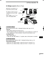
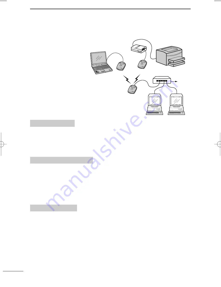
5-3 Bridge mode B
(Client Mode)
Set the AP-12 and the PC as
in the network shown at right.
• IP address of the PC should
already be set. (See Chapter
2 or 3)
• See Chapter 4 (p. 31) for
[AP-12 Manager] details.
• Follow the instruction manu-
al of the printer server when
connecting to the AP-12.
(Usually, a crossover cable
is used.)
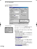
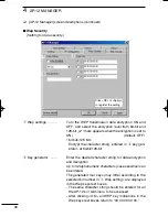
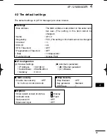
Set the following item in [AP-12 Manager] Settings screen. (p. 33)
• ESS ID:
Set the same ID.
- Check the “Auto Rate Fallback” (“
✓
” is appears) when communication is unstable.
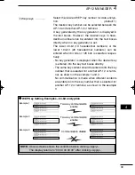
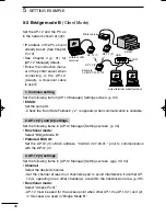
1. Common setting
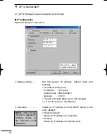
Set the following items in [AP-12 Manager] Settings screen. (p. 34)
• Functional mode:
Select “Bridge Mode B.”
• Preferred BSS ID:
Set the AP-12 (3)’s MAC address, “00-90-C7-27-00-01,” prior to communication
with the AP-12 (3).
2. AP-12 (1) and (2) settings
Set the following items in [AP-12 Manager] Settings screen. (pgs. 33, 34)
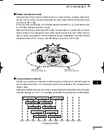
• Channel:
Select the desired channel.
- Set the channel at least four channels apart to avoid interference if another AP-
12(s), operating on an other channel(s), are within the transmission area. (p. 35)
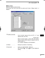
• Functional mode:
Select “Access Point.”
- AP-12 must be used for the access point when other AP-12s (AP-12 (1) and (2),
in this case) are used in “Bridge Mode B.”
3. AP-12 (3) settings
AP-12 (2)
AP-12 (3)
AP-12 (1)
HUB
Printer
Printer server
To LAN
wireless LAN
terminal
wired terminal
wired terminal
Example
00-90-C7-27-00-01
AP-12_USA 02.7.26 9:32 AM Page 48 (1,1)
Summary of Contents for AP-12
Page 2: ......
Page 14: ......
Page 44: ......
Page 64: ......
Page 86: ...MEMO ...
Page 87: ...MEMO ...
Page 88: ...1 1 32 Kamiminami Hirano ku Osaka 547 0003 Japan A 6165G 1EX Printed in Japan 2002 Icom Inc ...


