background image


MIN

MAX

7

W

W

21°C

32°C

Ic

em

ak

er

F

12

5C

 -

 Ic

em

at

ic

 -

 0

00

.in

dd

O

O

=

?

OO=?

O

O

=

?

O

O

=

?`

OO=?

OO=?

OO=?

O

O

=

?

O

O

=

?

O

O

=

?

OO=?

O

O

=

?

O

O

=

?

Raffreddamento ad aria  Air Cooled Unit

Raffreddamento ad acqua - Water Cooled Unit

Temp. aria  

Air Temp.

Temp. acqua / Water Temp.

Temp. aria  

Air Temp.

Temp. acqua / Water Temp.

°C

32°

21°

15°

10°

°C

32°

21°

15°

10°

°F

90°

70°

60°

50°

°F

90°

70°

60°

50°

10°

102

111

115

120

10°

97

108

117

120

50°

224

245

253

264

50°

214

238

258

264

21°

95

104

108

110

21°

95

105

115

117

70°

209

229

238

242

70°

209

231

253

258

32°

84

90

94

97

32°

90

100

107

110

90°

185

198

207

214

90°

198

220

236

242

38°

75

81

85

87

38°

87

97

102

105

100°

165

179

187

192

100°

192

214

225

231

F125C 

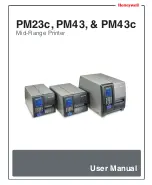
Fabbricatori di ghiaccio Granulari : F80C - F125C - F120 - F200 - SF300 - SF500 - SFN1000

Ice Flaker Machines  : 

F80C - F125C - F120 - F200 - SF300 - SF500 - SFN1000

120kg - 264lbs

S

A

V

ENER

G

Y

DATI TECNICI - SPECIFICATIONS

Ä

Ä

+ C°
 - C°

Ä

Back Inlet/outlet 

Ingressi/Uscite Posteriori

Ä

F80C - F125C - F120 - F200 - SF300 - SF500 - SFN1000

Fabbricatori di ghiaccio Granular

Ice Flaker Machines  : 


F80C - F125C - F120 - F200 - SF300 - SF500 - SFN1000

F120 - 

F125C - 

F80C - 

i : 

Fabbricatori di ghiaccio Granular


F80C - F125C - F120 - F200 - SF300 - SF500 - SFN1000

SFN1000

SF500 - 

SF300 - 

F200 - 

F120 - 


g - 264lbs

120k

SFN1000

F125C 


g - 264lbs

F125C 


 - C°

+ C°

A

  F125C 

COMP

   F125C W

COND.


W

W

Kwh/100Kg

FUSE

ABS. W

. W

COMP

P. 

TECNICI - SPECIFICA

TI 

DA

AT  

10.4

10

490

1228

8.0

10

430

1228


7

21°C

32°C

kg

Lbs

kg

l/h

Kwh/100Kg

TIONS


ICA


ATIONS

74

141

64

4,6

10.4

74

141

64

72.4

8.0


g - 264lbs

Lbs

kg

163

74

163

74


PRODUZIONE DI GHIACCIO - ICE PRODUCTION   

24 h

24 

24  h

Percentuale acqua residua nel ghiaccio dal 18 al 20%

70°

90°

°F

21°

32°

°C

emp. ac


T

Temp. acqua / W

emp.

Air T

 Temp.

aria

emp. 

T

Te


Raffreddamento ad aria  


PRODUZIONE DI GHIACCIO - ICE PRODUCTION   

Ice contains 18-20% residual water 

Percentuale acqua residua nel ghiaccio dal 18 al 20%

°F

50°

60°

70°

°C

10°

15°

21°

emp

Air T

 Temp.

aria

emp. 

T

Te


emp.

T

Temp.

ater 

  cqua / W


   Water 

Raffreddamento ad acqua - W

Air Cooled Unit

Raffreddamento ad aria  


kg/24h

PRODUZIONE DI GHIACCIO - ICE PRODUCTION   

- lbs/24h

Ice contains 18-20% residual water 

Percentuale acqua residua nel ghiaccio dal 18 al 20%

50°

60°

70°

90°

15°

21°

32°

emp.

T

ater 

emp. acqua / W


   Water 

T

emp.

aria

ater Cooled 

eddamento ad acqua - W


   Water Cooled Unit


- lbs/24h

DIMENSIONI - DIMENSIONS

A' DEPOSI

ACIT

TA' DEPOSIT

CAP

PACIT

50°

10°

ater Cooled Unit

WxDxH(in):26 12/16" x 20 1/16" x 39 6/16"

LxPxH(mm):  680 x 510 x 1000

27 kg  -  60 lbs


DIMENSIONI - DIMENSIONS

ACITY

O - BIN CAP


PACITY

A' DEPOSIT

WxDxH(in):26 12/16" x 20 1/16" x 39 6/16"

LxPxH(mm):  680 x 510 x 1000

27 kg  -  60 lbs


MARCHI - MARKS

179

111

104

90

81

165

100°

198

75

38°

185

90°

229

84

32°

209

70°

245

95

21°

224

50°

102

10°


CONSUMI - ENERGY

100°

120

10°

110

21°

97

32°

87

38°

192

187

179

90°

85

81

214

207

198

70°

94

90

242

238

229

50°

108

104

264

253

245

115

111


TECNOLOGIE-TECHNOLOGIES 

105

231

225

214

192

242

102

97

87

110

236

220

198

258

107

100

90

117

253

231

209

264

115

105

95

120

258

238

214

117

108

97


TECNOLOGIE-TECHNOLOGIES 

MIN

10°C (50°F)

5 C (41 F)

5


5°  

C  (4

 (4

  41


°


F


)

10%

100%

105

231

242

110

258

117

264

120

222200-224

2440/

0//550/

0/1

/1

220 240/50/1


MAX

40 C (104°F)

4


40


0°  

°C  (

 (1

  04

  04


F


)

35 C (95 F)

3


35


5°C 

C  (

 (9

  95

  5°


F)


)

+1 %

+100%

R1134

344a

R134


=

O

O


?

O


?

=

O

O

?

=

O

O

S

A

V

E

ENER

G

YY

G

RRGRRG

ER

ER

E

ER

N

E

E

V

E

V

E

VV

E

A

S


10%

-1100%

r (14 p )


 B  


 Ba  


  ar 


 (1  


  1  


  4 


 p


 ps


  si)


)

?

=

O

O


+10%

+100%

r (70 psi)


 B  


 Ba  


  ar 


 (  


 (70 psi)


  70 


 p


 ps


  si)


  i)

potabile

Attacco entrata acqua 

Ä

3/4" Gas

connection

ater condenser inlet 

W

Water condenser inlet 

condensazione

Attacco entrata acqua 


Ic

em

ak

er

F

12

5C

 -

 Ic

em

at

ic

 -

 0

00

.in

dd

?

=

O

O


?

=

O

O


?

?

?

?

?


?

?

=

O

O


Ä

Ä

 - C°

+ C°

Ä

 Ø 20 mm

nection

-

ater outlet con

W

Water outlet con

acqua

Attacco scarico 

3/4" Gas

connection

ater potable inlet 

W

Water potable inlet 

potabile

 Ø 20 mm

condensation

ater 

connection-W

Water 

ater outlet 

W

Water outlet 

acqua

condensazione ad 

Uscita acqua 


Ic

em

ak

er

F

12

5C

 -

 Ic

em

at

ic

 -

 0

00

.in

dd


Vi  


ia 


 d  


 de  


  el 


 L


 Lav


  av


  vo


or


ro    


o,    


9   


 - 


   C


   C.  .  1

  7

  72

 172


    P


    P

 d  L o o    C P

V

V
I   


 - 


   3


    1


    03  


    033 


33 


 C


 Ca


  as


st


te


el


lf


fr


ra


an  


nc  


co 


e


en


ne  

et  

to  (T

 (T

  TV

  V)

o (TV)


 V


 V


 Veneto (TV)


 V


   31 3 C

o V

ITA

A Y    E

   U

   U

Y

Y

ALLLY

LY

ALLY

IT

T

TAL

TAL

T

TAL

`?

=

O

O


e  


el  


 +3  


 +3  


  39 


 0423 738452


 0423 738452


  423 


  23 


 7


 73


  384


  84


452


52

 +   4 3 73 452

T

T

Tel. +39 0423 738452

T  


T
F  


Fax 


ax 


 +3  


 +3  


  39 


 0423 72281


 0423 72281


  423 


  23 


 7


 722


  22


  281


111

F x +   4 3 722 1

=

O

O

=

O

O

=

O

O

=

O

O

=

O

O


iicceem

maattiicc@

@ccaasstteelm

maac.iit

@

w

ww ccaasstteellm

maacc.iit

ww

w.

=

O

O

Ingressi/Uscite Posteriori

Back Inlet/outlet 


Ingressi/Uscite Posteriori

Summary of Contents for F 125C

Page 1: ...2 05 2015 I NOSTRI IMPIANTI SONO CONFORMI ALLA DIRETTIVA 73 23 CEE 89 336 SERVICE MANUAL ELECTRONIC MODULAR FLAKERS AND SUPERFLAKERS F 80 C F 125 C F 120 F 200 SF 300 SF 500 SFN 1000 Gas R134a R 404a...

Page 2: ...S SONDA EVAPORATORE MALFUNZIONANTE BLINKING CLIGNOTANT LAMPEGGIANTE 6 OR 12 MONTHSWATER SYSTEM CLEANING REMIND according to the Jumper setting RAPPEL NETTOYAGE SYST ME HYDRAULIQUE APR S 6 OU 2 MOIS se...

Page 3: ...stallation pratice 13 OPERATING INSTRUCTIONS Start up 14 Operations checks 16 PRINCIPLE OF OPERATION how it works Water circuit 19 Refrigerant circuit 20 Mechanical system 22 Operating pressures 23 Co...

Page 4: ...ua nel ghiaccio dal 18 al 20 50 60 70 90 15 21 32 emp T ater emp acqua W Water T emp aria ater Cooled eddamento ad acqua W Water Cooled Unit lbs 24h DIMENSIONI DIMENSIONS A DEPOSI ACIT TA DEPOSIT CAP...

Page 5: ...er emp acqua W Water T emp aria ater Cooled eddamento ad acqua W Water Cooled Unit lbs 24h DIMENSIONI DIMENSIONS A DEPOSI ACIT TA DEPOSIT CAP PACIT 50 10 ater Cooled Unit WxDxH in 26 12 16 x 20 1 16 x...

Page 6: ...nto ad acqua W Air Cooled Unit Raffreddamento ad aria kg 24h PRODUZIONE DI GHIACCIO ICE PRODUCTION lbs 24h Ice contains 18 20 residual water Percentuale acqua residua nel ghiaccio dal 18 al 20 50 60 7...

Page 7: ...er Raffreddamento ad acqua W Air Cooled Unit Raffreddamento ad aria kg 24h PRODUZIONE DI GHIACCIO ICE PRODUCTION lbs 24h Ice contains 18 20 residual water Percentuale acqua residua nel ghiaccio dal 18...

Page 8: ...d acqua W Water Cooled Unit lbs 24h DIMENSIONI DIMENSIONS O SLOPE BIN DEPOSIT 50 10 ater Cooled Unit WxDxH in 21 3 16 x 26 2 16 x 25 10 16 LxPxH mm 538 x 663 x 650 DR140 DR320 D105 D155 D205 D255 D305...

Page 9: ...CE PRODUCTION lbs 24h Ice contains 18 20 residual water Percentuale acqua residua nel ghiaccio dal 18 al 20 50 60 70 90 15 21 32 emp T ater emp acqua W Water T emp aria ater Cooled eddamento ad acqua...

Page 10: ...DI GHIACCIO ICE PRODUCTION lbs 24h Ice contains 18 20 residual water Percentuale acqua residua nel ghiaccio dal 18 al 20 50 60 70 90 15 21 32 emp T ater emp acqua W Water T emp aria ater Cooled eddame...

Page 11: ...acking and skid Any severe damage noted should be reported to the delivering carrier and a concealed damage claim form filled in subjet to inspection of the contents with the carrier s representative...

Page 12: ...e bolts holding the shipping skid to the bin 3 Screw in the legs into the corresponding tap ped holes in the bin bottom and tighten to seat the legs well against the bin bottom 4 Connect the water dra...

Page 13: ...the ice drop area cover the edges of the opening with vinyl tape 7 Install the gasket on the bin top around ice drop opening of the bin top apply sealant along the inside of the gasket 8 Position and...

Page 14: ...ppropriate water filter or conditioner WATER SUPPLY WATER COOLED MODELS The water cooled versions of Ice Makers requi re two separate inlet water supplies one for the water making the flaker ice and t...

Page 15: ...d possible fai lure 9 Have the bin liner and cabinet been wiped clean 10Has the owner user been given the User Manual and been instructed on the importan ce of periodic maintenance checks 11Has the Ma...

Page 16: ...ser fins Fig 2 C After 2 or 3 minutes from the compressor start up observe that flaker ice begins drop ping off the ice spout to fall through the ice chute into the storage bin OPERATING INSTRUCTIONS...

Page 17: ...15...

Page 18: ...s necessary to unplug and plug in again to restart the machine The unit before resuming the normal operation will go through the usual 3 minutes STAND BY period NOTE On air cooled models the condenser...

Page 19: ...up of the ice into the ice chute till it cuts the light beam of the sensing eyes This interruption will cause an imme diate blinking of the Bin Full YELLOW LED located on the front of the P C Board an...

Page 20: ...rd Button The Optical Ice Level Control is now recali brated Check for the correct operation of the Optical Ice Level Control by plasing a hand full of ice in between the two eyes The Bin Full yellow...

Page 21: ...ge of water The float reservoir is positioned at the side of the freezing at such an height to be able to maintain a constant water level The water flows from the reservoir into the bottom inlet of th...

Page 22: ...nt exchanges heatwith the one flowing into the capillary tube warmer befo rebeingsuckedinto thecompressor to be recircu lated The refrigerant head pressure is kept between two pre set values 8 9 bar 1...

Page 23: ...event the unit from opera ting in abnormal and dangerous conditions When the ice maker stops on account of this protective device there is a simultaneous glowing of the RED LED warning the user of the...

Page 24: ...will restart automatically In case the unit trips OFF again in alarm for 3 times in 3 hours themachine SHUTSOFF DEFINITIVELY NOTE In the event the gear motor one of the two on MF 66 will tend to rotat...

Page 25: ...GERANT CHARGE R 134 A Air cooled Water cooled F 80C 300 gr 300 gr F 125C 400 gr 300 gr F 120 440 gr 400 gr OPERATING PRESSURES With 21 C ambient temperature Discharge pressure 8 9 bar 8 5 bar Suction...

Page 26: ...eater resi stence to the current flow electrical conduc tivity lower than 30 mS This sensor system causes the shutoff of the machine to protect it from running without water or with an inadequate wate...

Page 27: ...s in the chute When the light beam is interrupted the Bin Full YELLOW LED located in the front of the P C BOARD blinks in case the light beam gets interrupted for as long as 6 seconds the ice machine...

Page 28: ...the sensors in order to control the operation of the different electrical components of the ice maker com pressor gear motor etc The five LEDS pla ced in a row in the front of the P C BOARD monitor t...

Page 29: ...Board button for more of 5 seconds with machine in operation till the switching OFF of the two YELLOW Leds J6 60 70 C Set up of the Safety Condensing Temperature Sensor JUMP IN 70 C JUMP OUT 60 C H I...

Page 30: ...bearing every six months L GEAR MOTOR Two on SFN 1000 The gear motor is made of a single phase electric motor with permanent capacitor directly fitted on a gear box The drive motor rotor is kept alig...

Page 31: ...e rear panels and on SFN1000 remove the front top and left side panels 2 Unloose the three screws securing the pla stic cover to the top of the gear motor and remove it 3 Unloose the two screws securi...

Page 32: ...ssy to the alumi nium adaptor 11 Raise the freezer assy off the adaptor secu re it out of the way to allow room to work On F120 F200 using a suitable lenght and size wooden dowel or stick inserted thr...

Page 33: ...sor 4 Trace and disconnect the electric wires leads of the drive motor Lift and remove the entire gear motor assembly 5 To install the replacement gear motor assy follow the above steps in reverse E R...

Page 34: ...D 2 2 mm 480 W 3 2 A 18 A 0 200 A 11 5 KWH 24 HR F120 A W 230 50 1 R134a 440 400 gr 2600 mm D int 1 00 D 2 2 mm 350 W 2 1 A 9 1 A 0 300 A 8 5 KWH 24 HR F200 A W 230 50 1 R404a 660 520 gr 2600 mm D 1 2...

Page 35: ...35 WIRING DIAGRAM F 80C Air cooled 220 240 50 1...

Page 36: ...36 WIRING DIAGRAM F 80C Water cooled 220 240 50 1...

Page 37: ...37 WIRING DIAGRAM F 125C Air water cooled 220 240 50 1...

Page 38: ...38 WIRING DIAGRAM F 120 F 200 Air water cooled 220 240 50 1...

Page 39: ...39 WIRING DIAGRAM SF 300 SF 500 Air water cooled 220 240 50 1...

Page 40: ...40 WIRING DIAGRAM SF 500 Air water cooled 400 50 3...

Page 41: ...41 WIRING DIAGRAM SFN 1000 Air water cooled 400 50 3...

Page 42: ...e P C Board Check wiring Replace or clean ice level control See remedies for shortage of water Install a mineral salt metering device Dirty condenser Clean INOPERATIVE fan motor Replace Move unit in w...

Page 43: ...asten hose clamp Check and adjust float valve setting screw Tighten screws holding the spout Excessive noise or chatte ring Mineral or scale deposit on auger and inner freezer walls Low suction pressu...

Page 44: ...ved with the help of a bit of cleaner 7 With the ice machine and fan motor OFF on air cooled models clean condenser using vacuum cleaner whisk broom or non metallic brush taking care to do not damage...

Page 45: ...into the pan Then refit the water hose to the freezer water inlet port 7 Prepare the cleaning solution in a plastic container 8 Pour the cleaning solution into the water reservoir 9 Wait till the mac...

Page 46: ...ctly the cover on the float reser voir NOTE The ice produced with the decalcifi cation solution is yellowish and smooth In this phase there are loud noises from the freezer due to the rubbing between...

Page 47: ......

Page 48: ...Via del Lavoro 9 C P 172 I 31033 Castelfranco Veneto TV Italy Tel 39 0423 738455 Fax 39 0423 722811 E mail service castelmac it Web site www castelmac it Cod 71503496 0 Rev 002 05 2015...

Reviews: