


142
ICC
cause the service object to run past the end of the database. The highest valid
database address, therefore, depends on the number of parameters to be
accessed.
Multiplier
This field is the amount that associated network values are scaled by prior to
being stored into the database or after being retrieved from the database. Upon
retrieval from the database, raw data is multiplied by the multiplier to produce a
network value (to be sent to a controller). Similarly, network values (read from a
controller) are divided by the multiplier before being stored into the database.
This value is ignored for display parameters.
Note that the multiplier imposes range limitations on network data values. For
example, if the multiplier is 0.01, then the network data can achieve a maximum
value of only 655 (since 65535 is the maximum value that can be stored in 16 bits
in the database).
Read Enable and Function Code Selection
Check
Read
to enable reading (the service object will continuously read from the
controller unless a pending
Write
exists). When reads are enabled, the desired
read
Function Code
can be selected in the drop-down box.
Write Enable and Function Code Selection
Check
Write
to enable writing (when values encompassed by this service object
change in the gateway’s database, these changes will be written down to the
targeted controller). When writes are enabled, the desired write
Function Code
can be selected in the drop-down box.
Service Object Status
If it is desired to reflect the status of this service object, check the
Reflect Status
checkbox and enter a database
address
between 0 and 4080 (0x0 – 0xFF0) at
which to store the status information. For more information on reflecting the
status of service objects, refer to section 8.5.2.
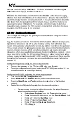
8.8.15.3
Configuration Example
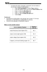
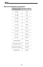
This example will configure the gateway for accessing a Supervisor controller via
the Sullair Master driver. Say, for instance, we wish to monitor P1 – P4, T1 – T5,
and the run status. These data items are located at parameters 107 – 110, 111 –
115, and 103 respectively (refer to section 11.14 for a list of Supervisor
parameters with indexes of 100+). We also wish to control the unload pressure,
load pressure delta, and unload time, located at parameters 5, 6, and 7
respectively.
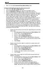
Configure the gateway using the above requirements
•
Connect the gateway to the PC via a USB mini type-B cable.
•
Open the configuration utility and select the ETH-1000 (see section 8.1 for
more information on selecting a device).