background image

v


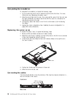
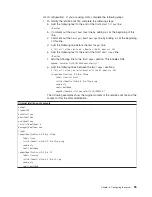
If


you


use


an


integrated


SAS/SATA


controller


with


RAID


capabilities


to


configure


a


RAID


1


(mirrored)


array


after


you


have


installed


the


operating


system,


you


will


lose


access


to


any


data


or


applications


that


were


previously


stored


on


the


secondary


drive


of


the


mirrored


pair.


v


If


you


install


a


different


type


of


RAID


controller,


see


the


documentation


that


comes


with


the


controller


for


information


about


viewing


and


changing


SAS/SATA


settings


for


attached


devices.

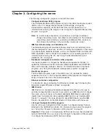
Starting


the


LSI


Logic


Configuration


Utility


program


To


start


the


LSI


Logic


Configuration


Utility


program,


complete


the


following


steps:


1.


Turn


on


the


server.


2.


When


the


prompt


Press


CTRL-C


to


start


LSI


Logic


Configuration


Utility......


is


displayed,


press


Ctrl+C.


If


you


have


set


an


administrator


password,


you


are


prompted


to


type


the


password.


3.


To


select


a


controller


(channel)


from


the


list


of


adapters,


use


the


arrow


keys


and


press


Enter.


4.


To


change


the


settings


of


the


selected


items,


follow


the


instructions


on


the


screen.

When


you


have


finished


changing


settings,


press


Esc


to


exit


from


the


program;


select


Save


to


save


the


settings


that


you


have


changed.


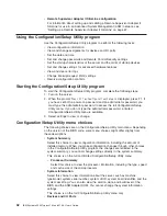
Formatting


a


SAS/SATA


hard


disk


drive


Low-level


formatting


removes


all


data


from


the


hard


disk.


If


there


is


data


on


the


disk


that


you


want


to


save,


back


up


the


hard


disk


before


you


perform


this


procedure.

Note:


Before


you


format


a


SAS/SATA


hard


disk,


make


sure


that


the


disk


is


not


part


of


a


mirrored


pair.


From


the


list


of


adapters,


select


the


controller


(channel)


for


the


drive


that


you


want


to


format.


Select


SAS


Topology

;


then,


select


Drive

and


press


Alt+D

.


To


format


a


drive,


complete


the


following


steps:


1.


From


the


list


of


adapters,


select


the


controller


(channel)


for


the


drive


that


you


want


to


format


and


press


Enter.


2.


Select


SAS


Topology


and


press


Enter.


3.


Select


Direct


Attach


Devices


and


press


Enter.


4.


To


highlight


the


drive


that


you


want


to


format,


use


the


Up


Arrow


and


Down


Arrow


keys.


To


scroll


left


and


right,


use


the


Left


Arrow


and


Right


Arrow


keys


or


the


End


key.


5.


To


start


the


love-level


formatting


operation,


select


Format


and


press


Enter.

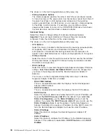
Creating


a


RAID


array


of


SAS/SATA


hard


disk


drives


To


create


a


RAID


array


of


SAS/SATA


hard


disk


drives,


complete


the


following


steps:


1.


From


the


list


of


adapters,


select


the


controller


(channel)


for


the


drives


that


you


want


to


mirror.


2.


Select


RAID


Properties

.


3.


Select


the


type


of


array


that


you


want


to


create.


4.


Use


the


arrow


keys


to


highlight


the


first


drive


in


the


pair;


then,


press


the


Minus


(-)


or


Plus


(+)


key


until


you


have


selected


all


the


drives


for


your


array.


5.


Press


C


to


create


the


disk


array.


52


IBM


System


x3350


Types


4192


and


4193:


User’s


Guide

Summary of Contents for x3350 - System - 4192

Page 1: ...IBM System x3350 Types 4192 and 4193 User s Guide...

Page 2: ......

Page 3: ...IBM System x3350 Types 4192 and 4193 User s Guide...

Page 4: ...general information in Notices on page 71 First Edition January 2008 Copyright International Business Machines Corporation 2008 All rights reserved US Government Users Restricted Rights Use duplicati...

Page 5: ...hot swap power supply 24 Installing a Y power cable 25 Installing a hard disk drive 26 Installing a hot swap hard disk drive 26 Installing a simple swap hard disk drive 27 Installing an adapter 28 Ins...

Page 6: ...nagement controller utility programs 63 Enabling the Broadcom Gigabit Ethernet Utility program 66 Configuring the Broadcom Gigabit Ethernet controller 66 Updating IBM Director 67 Setting up a Remote S...

Page 7: ...n tuotteen lue turvaohjeet kohdasta Safety Information Avant d installer ce produit lisez les consignes de s curit Vor der Installation dieses Produkts die Sicherheitshinweise lesen Prima di installar...

Page 8: ...Information document For example if a caution statement is labeled Statement 1 translations for that caution statement are in the Safety Information document under Statement 1 Be sure to read all cau...

Page 9: ...quipment when there is evidence of fire water or structural damage v Disconnect the attached power cords telecommunications systems networks and modems before you open the device covers unless instruc...

Page 10: ...thium battery replace it only with the same module type made by the same manufacturer The battery contains lithium and can explode if not properly used handled or disposed of Do not v Throw or immerse...

Page 11: ...he device v Use of controls or adjustments or performance of procedures other than those specified herein might result in hazardous radiation exposure DANGER Some laser products contain an embedded Cl...

Page 12: ...on the device and the power switch on the power supply do not turn off the electrical current supplied to the device The device also might have more than one power cord To remove all electrical curren...

Page 13: ...a power supply or any part that has the following label attached Hazardous voltage current and energy levels are present inside any component that has this label attached There are no serviceable part...

Page 14: ...Statement 26 CAUTION Do not place any object on top of rack mounted devices xii IBM System x3350 Types 4192 and 4193 User s Guide...

Page 15: ...including how to install supported optional devices and how to configure the server The following documentation also comes with the server v Installation Guide This printed document contains instructi...

Page 16: ...tem x3350 and click Continue Notices and statements used in this document The caution and danger statements that appear in this document are also in the multilingual Safety Information document which...

Page 17: ...ng information is a summary of the features and specifications of the server Depending on the server model some features might not be available or some specifications might not apply Chapter 1 The Sys...

Page 18: ...ID hot swap SAS SATA models Acoustical noise emissions v Sound power idling 6 5 bels maximum v Sound power operating 6 5 bels maximum Environment v Air temperature Server on 10 to 35 C 50 0 to 95 F al...

Page 19: ...processor based server powerful scalable and reliable For more information see http www ibm com servers eserver xseries xarchitecture enterprise index html v Large system memory capacity The memory b...

Page 20: ...iguration The redundant cooling of the fans in the server enables continued operation if one of the fans fails The server comes with one 450 watt hot swap power supply and four fans You can order the...

Page 21: ...r management compliance with Advanced Configuration and Power Interface ACPI v Power on self test POST v Predictive Failure Analysis PFA alerts v Redundant Ethernet capabilities with failover support...

Page 22: ...costs For more information about IBM Director see the documentation on the IBM Director CD that comes with the server the IBM Director Information Center at http publib boulder ibm com infocenter ese...

Page 23: ...configuration that you have v The following illustration shows the operator information panel This panel contains controls and LEDs that indicate the status of the server Power on LED green System lo...

Page 24: ...ives is in use Notes 1 For a SAS drive a hard disk drive activity LED is shown in two places on the hard disk drive and on the operator information panel 2 For a SATA drive hard disk drive activity is...

Page 25: ...tem x Documentation CD v System error LED When this LED is lit it indicates that a system error has occurred An LED on the light path diagnostics panel is also lit to help isolate the error v Power on...

Page 26: ...cted to power You can turn on the server and start the operating system by pressing the power control button The server can also be turned on in any of the following ways v If a power failure occurs w...

Page 27: ...y shutdown of the operating system the server will turn off automatically v You can press the power control button to start an orderly shutdown of the operating system and turn off the server if your...

Page 28: ...14 IBM System x3350 Types 4192 and 4193 User s Guide...

Page 29: ...S hard disk drive Air baffle 3 5 inch simple swap SATA hard disk drive 3 5 inch filler panel simple swap 3 5 inch filler panel hot swap 2 5 inch hard disk drive backplane 2 5 inch hard disk drive cage...

Page 30: ...1 connector Mini SAS SATA controller connector Microprocessor connector USB connectors Video connector Fan 2 connector IDE connector Operator information panel connector Fan 3 connector Fan 4 connecto...

Page 31: ...ation shows the external input output connectors on the system board Video connector Serial connector USB 1 connector USB 2 connector Ethernet 1 connector Ethernet 2 connector Ethernet connector Syste...

Page 32: ...Table 2 System board jumpers Jumper Description Clear CMOS JP1 v Pins 1 and 2 Keep CMOS data default v Pins 2 and 3 Clear the CMOS data which clears the power on password and administrator password Bo...

Page 33: ...error LED DIMM 1 LED error DIMM 2 LED error DIMM 3 LED error DIMM 4 LED error Microprocessor LED System board battery error LED PCI Express slot 1 error LED Fan 3 error LED Fan 4 error LED Fan 5 error...

Page 34: ...s in Handling static sensitive devices on page 22 This information will help you work safely v When you install your new server take the opportunity to download and apply the most recent firmware upda...

Page 35: ...Phillips screwdriver available v You do not have to turn off the server to install or replace hot swap power supplies hot swap fans or hot plug Universal Serial Bus USB devices However you must turn o...

Page 36: ...you are working inside the server v Do not allow your necktie or scarf to hang inside the server v Remove jewelry such as bracelets necklaces rings and loose fitting wrist watches v Remove items from...

Page 37: ...the server cover complete the following steps 1 Read the safety information that begins on page v and Installation guidelines on page 20 2 If you are planning to install or remove a memory module PCI...

Page 38: ...a power supply failure the redundant power supply continues to power the system The server supports a maximum of two power supplies Note If you are using a Y power cable between two servers that act...

Page 39: ...ack 6 Connect the cable to through the cable management arm if installed 7 Connect the other end of the power cord to a properly grounded electrical outlet 8 Make sure that the ac power LED and the dc...

Page 40: ...s in these servers v The 3 5 inch server models support two hot swap SAS or hot swap SATA hard disk drives You can install only 3 5 inch hot swap SAS or hot swap SATA drives in these servers v The sim...

Page 41: ...hat drive is faulty and must be replaced If the green hard disk drive activity LED is flashing the drive is being accessed Note If the server has a RAID controller or adapter you might have to reconfi...

Page 42: ...e instructions that come with the adapter v The adapter slots are on the riser card assemblies You must first remove the riser card assemblies to access the adapter slots v The server provides two PCI...

Page 43: ...Set any jumpers or switches on the adapter as directed by the adapter manufacturer 8 Insert the adapter into the riser card assembly aligning the connector on the adapter with the connector on the ri...

Page 44: ...issions characteristics of the server and ensures proper cooling of server components 5 Touch the static protective package that contains the controller to any unpainted metal surface on the server Th...

Page 45: ...ecause some memory is reserved for system operation the actual usable memory size that is reported by the operating system is less than the total installed size v The server comes with a minimum of tw...

Page 46: ...econd pair Remarks DIMM 1 DIMM 3 DIMM 2 DIMM 4 Single rank Single rank Single rank Single rank Single rank Single rank Double rank Double rank Recommend this configuration as the first choice Double r...

Page 47: ...nnector 7 Firmly press the DIMM straight down into the connector by applying pressure on both ends of the DIMM simultaneously The retaining clips snap into the locked position when the DIMM is firmly...

Page 48: ...rver and peripheral devices and disconnect the power cord and all external cables Remove the cover see Removing the server cover on page 23 Hard disk drive assembly Filler panel 3 Pull the hard disk d...

Page 49: ...ard c Press the controller firmly onto the alignment pins until it clicks into place Make sure that the top of each alignment pin has expanded to hold the controller securely in place d Push the contr...

Page 50: ...Adapter II SlimLine is installed the systems management Ethernet port on the rear of the server is active To install a Remote Supervisor Adapter II SlimLine complete the following steps 1 Read the saf...

Page 51: ...riser card assembly install it in slot 2 on the system board Make sure that the riser card assembly is fully seated in the riser card connector on the system board See the documentation that comes wi...

Page 52: ...page 39 for more information Replacing the server cover To replace the server cover complete the following steps 1 Make sure that all internal cables are routed correctly 2 Slide the cover forward ma...

Page 53: ...server configuration When you start the server for the first time after you add or remove a device you might receive a message that the configuration has changed The Configuration Setup Utility progra...

Page 54: ...For information about configuring the integrated Gigabit Ethernet controller see Configuring the Broadcom Gigabit Ethernet controller on page 66 40 IBM System x3350 Types 4192 and 4193 User s Guide...

Page 55: ...data record field replaceable unit SDR FRU data and to remotely manage a network For information about using these programs see Using the baseboard management controller on page 53 v Boot Menu program...

Page 56: ...Setup Utility menu If you do not type the administrator password a limited Configuration Setup Utility menu is available 3 Select settings to view or change Configuration Setup Utility menu choices Th...

Page 57: ...es that are installed in the server v Date and Time Select this choice to set the date and time in the server in 24 hour format hour minute second This choice is on the full Configuration Setup Utilit...

Page 58: ...ress devices configure PCI interrupt routing and enable or disable PCI ROM control execution RSA II Settings Select this choice to view and change Remote Supervisor Adapter II SlimLine settings Select...

Page 59: ...fication version BMC Firmware Version This is a nonselectable menu item that displays the BMC firmware version BMC Build Date This is a nonselectable menu item that displays the BMC firmware build dat...

Page 60: ...installed Select this choice to view the error messages in the Remote Supervisor Adapter II event error log Use the arrow keys to move among pages in the log Select Clear RSA II logs to clear the Rem...

Page 61: ...hen you turn on the server you must type the power on password to complete the system startup You can use any combination of up to seven characters A Z a z and 0 9 for the password If a power on passw...

Page 62: ...view the safety information that begins on page v 2 Turn off the server and peripheral devices and disconnect all power cords and external cables 3 Remove the cover See Removing the server cover on pa...

Page 63: ...a free image of the ServerGuide Setup and Installation CD or purchase the CD from the ServerGuide fulfillment Web site at http www ibm com systems management serverguide sub html To download the free...

Page 64: ...w the overview to learn about ServerGuide features v View the readme file to review installation tips for your operating system and adapter v Start the operating system installation You will need your...

Page 65: ...simple swap SATA hard disk drives Use the LSI Logic Configuration Utility program to perform the following tasks v Perform a low level format of a SAS SATA hard disk drive v Create an array of SAS SA...

Page 66: ...hard disk If there is data on the disk that you want to save back up the hard disk before you perform this procedure Note Before you format a SAS SATA hard disk make sure that the disk is not part of...

Page 67: ...other management functions Any standard Telnet client application can access the SOL connection Enabling and configuring SOL using the OSA SMBridge management utility program To enable and configure...

Page 68: ...console through an SOL session and directs Linux output to the serial console See the documentation for your specific Linux operating system type for information and instructions Use one of the follo...

Page 69: ...SOL append console ttyS0 19200n8 console tty1 g Add the following lines between the two image sections This will allow you to Interact with the OS boot via SOL image boot vmlinuz 2 4 9 e 12smp label l...

Page 70: ...perating system starts a LILO boot prompt is displayed instead of the graphical user interface Press Tab at this prompt to install all of the boot options that are listed To load the operating system...

Page 71: ...ed by anaconda Note that you do not have to rerun grub after making changes to this file NOTICE You have a boot partition This means that all kernel and initrd paths are relative to boot eg root hd0 0...

Page 72: ...root dev hda6 initrd initrd 2 4 9 e 12 img You must restart the Linux operating system after you complete these procedures for the changes to take effect and to enable SOL SUSE SLES 8 0 configuration...

Page 73: ...ntents Notes gfxmanu hd0 1 boot message color white blue black light gray default 0 timeout 8 title linux kernel hd0 1 boot vmlinuz root dev hda2 acpi oldboot vga 791 1 initrd hd0 1 boot initrd title...

Page 74: ...mpt then press Enter to display the current boot options for your server b In the Boot Entries section locate the boot entry ID for the section with an OS friendly name of Windows Server 2003 Standard...

Page 75: ...disk 0 rdisk 0 partition 1 WINDOWS OS Load Options fastdetect redirect You must restart the Windows 2003 operating system after you complete this procedure for the changes to take effect and to enabl...

Page 76: ...es 1 Go to http www ibm com systems support Download the utility program and create the OSA BMC Management Utility CD 2 Insert the OSA BMC Management Utility CD into the drive 3 Type mount mnt cdrom 4...

Page 77: ...baseboard management controller setup utility program complete the following steps 1 Turn on the server 2 Insert the setup utility diskette into the diskette drive 3 From a command line type bmc and...

Page 78: ...te utility program to download a baseboard management controller firmware update This program updates the baseboard management controller firmware only and does not affect any device drivers Important...

Page 79: ...kette into the diskette drive 3 From a command line type fsloader and press Enter Using the OSA SMBridge management utility program Use the OSA SMBridge management utility program to remotely manage a...

Page 80: ...orts and press Enter 2 Select Planar Ethernet 1 and Planar Ethernet 2 and use the Right Arrow key to set them to enabled 3 Select Save Settings and press Enter Configuring the Broadcom Gigabit Etherne...

Page 81: ...tall any applicable updates or interim fixes for the server a Go to http www ibm com systems support b Under Product Support click System x c Under Popular links click Software and device drivers d Cl...

Page 82: ...age the server remotely through the Remote Supervisor Adapter II SlimLine by using one of the user interfaces and one of the connection methods that are described in the following table Table 5 Cablin...

Page 83: ...ns in the Remote Supervisor Adapter II readme file that you downloaded to install the software and firmware 8 Restart the server after the software and firmware are installed Completing the setup See...

Page 84: ...70 IBM System x3350 Types 4192 and 4193 User s Guide...

Page 85: ...LUDING BUT NOT LIMITED TO THE IMPLIED WARRANTIES OF NON INFRINGEMENT MERCHANTABILITY OR FITNESS FOR A PARTICULAR PURPOSE Some states do not allow disclaimer of express or implied warranties in certain...

Page 86: ...Red Hat the Red Hat Shadow Man logo and all Red Hat based trademarks and logos are trademarks or registered trademarks of Red Hat Inc in the United States and other countries Other company product or...

Page 87: ...mation on IBM product recycling offerings can be found on IBM s Internet site at http www ibm com ibm environment products index shtml Esta unidad debe reciclarse o desecharse de acuerdo con lo establ...

Page 88: ...ny potential effects of EEE on the environment and human health due to the potential presence of hazardous substances in EEE For proper collection and treatment contact your local IBM representative B...

Page 89: ...vie selon cette norme In accordance with the European Directive 2006 66 EC batteries and accumulators are labeled to indicate that they are to be collected separately and recycled at end of life The l...

Page 90: ...isual display work place devices according to clause 2 of the German Ordinance for Work with Visual Display Units Das Produkt ist nicht f r den Einsatz an Bildschirmarbeitspl tzen im Sinne 2 der Bilds...

Page 91: ...ew 38 caution statements 2 CD drive specifications 3 CD RW DVD drive activity LED 10 eject button 10 CD RW DVD drive specifications 4 clear CMOS 48 CLI command line interface mode 65 CMOS clear 48 com...

Page 92: ...expansion slots 20 F fans 4 6 features server 3 5 ServerGuide 49 firmware updating 2 firmware code updating 63 Formatting hard disk drives 52 G gloss statement Germany 76 H handling static sensitive d...

Page 93: ...51 NMI button 11 notes 2 notes important 72 notices 71 notices and statements 2 O online publications 2 operator information panel 9 optional device installation guidelines 20 static sensitive 22 opti...

Page 94: ...and Installation CD 49 using 49 Web site 49 ServerGuide CD 5 ServerGuide setup and installation 41 serviceability 7 setting up your server 50 setup and configuration ServerGuide 50 sever configuratio...

Page 95: ...ting the firmware code 63 USB connector 10 rear 11 V video specifications 3 video connector front 10 rear 11 video controller specifications 4 W Wake on LAN feature 12 Web site IBM System x3200 produc...

Page 96: ...82 IBM System x3350 Types 4192 and 4193 User s Guide...

Page 97: ......

Page 98: ...Part Number 43W7070 Printed in USA 1P P N 43W7070...

Reviews: