background image

 4

IBM FAStT200 and FAStT200 HA Storage Servers Installation and User’s Guide


Storage server components

The following sections show the components of the storage server.

The hot-swap features of the storage server enable you to remove and replace hard 
disk drives, power supplies, RAID controllers, and fans without turning off the storage 
server. Therefore, you can maintain the availability of your system while a hot-swap 
device is removed, installed, or replaced.

Front view

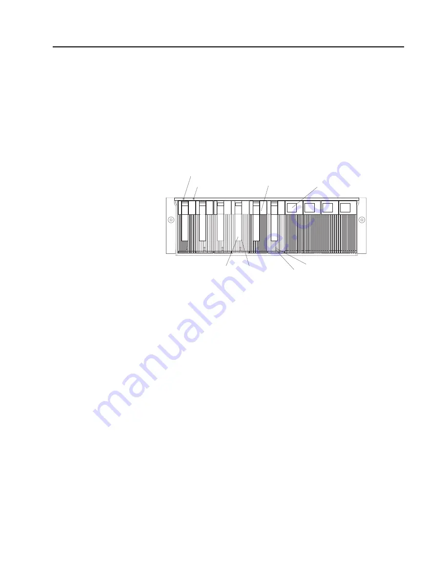
The following illustration shows the components and controls on the front of the 
storage server.

Power-on LED

When on, this green light indicates that the unit has good dc power.

General-system-error LED

When on, this amber LED indicates that the storage server has a fault, such 
as in a power supply, fan unit, or hard disk drive.

Note:

If the General-system-error LED is on continuously (not flashing), there 
is a problem with the storage server. Use the storage-management 
software to diagnose and repair the problem. For more information, 
see “Checking the LEDs” on page 29.

Hot-swap drive CRU

You can install up to 10 hot-swap drive 

customer replaceable units

 (CRUs) in 

the storage server. Each drive CRU consists of a hard disk drive and tray.

Filler panel

The storage server comes without drives installed and contains filler panels in 
the unused drive bays. Before installing new drives, you must remove the 
filler panels and save them. Each of the 10 bays must always contain either a 
filler panel or a drive CRU. Each filler panel contains a filler piece for use with 
a slim drive.

Drive activity LED

Each drive CRU has a green Drive activity LED. When flashing, this green 
LED indicates drive activity. When on continuously, this green LED indicates 
that the drive is properly installed.

Drive fault LED

Each drive CRU has an amber Drive fault LED. When on, this amber LED 
indicates a drive failure. When flashing, this amber LED indicates that a drive 
identify or rebuild process is in progress.

Drive activity LED

Hot-swap
drive CRU

Tray handle

Latch

Drive fault LED

Power-on LED

General-system-
error LED

Filler panel

Summary of Contents for TotalStorage FAStT200

Page 1: ...IBM IBM FAStT200 and FAStT200 HA Storage Servers Installation and User s Guide SC21 P877 50 ...

Page 2: ......

Page 3: ...IBM IBM FAStT200 and FAStT200 HA Storage Servers Installation and User s Guide SC21 P877 50 ...

Page 4: ...t warranties and notices on page 77 First Edition September 2000 COPYRIGHT INTERNATIONAL BUSINESS MACHINES CORPORATION 2000 All rights reserved Note to U S Government Users Documentation related to restricted rights Use duplication or disclosure is subject to restrictions set forth in GSA ADP Schedule Contract with IBM Corp ...

Page 5: ...irjanen ennen kuin asennat tämän tuotteen Avant de procéder à l installation de ce produit lisez le manuel Safety Information Vor Beginn der Installation die Broschüre mit Sicherheitshinweisen lesen Prima di installare questo prodotto leggere l opuscolo contenente le informazioni sulla sicurezza Pred instalací tohoto produktu si prectete prírucku bezpecnostních instrukcí Przed zainstalowaniem tego...

Page 6: ...oduto leia o folheto Informações sobre Segurança Antes de instalar este producto lea la Información de Seguridad Läs säkerhetsinformationen innan du installerar den här produkten Перед установкой продукта прочтите брошюру по технике безопасности Safety Information Pred inštaláciou tohto produktu si preG ítajte InformaG nú brožúrku o bezpeG nosti Preden namestite ta izdelek preberite knjižico Varno...

Page 7: ...ny equipment when there is evidence of fire water or structural damage Disconnect the attached power cords telecommunications systems networks and modems before you open the device covers unless instructed otherwise in the installation and configuration procedures Connect and disconnect cables as described in the following table when installing moving or opening covers on this product or attached ...

Page 8: ...n There are no serviceable parts inside the device Use of controls or adjustments or performance of procedures other than those specified herein might result in hazardous radiation exposure Danger Some laser products contain an embedded Class 3A or Class 3B laser diode Note the following Laser radiation when open Do not stare into the beam do not view directly with optical instruments and avoid di...

Page 9: ...ent 5 CAUTION The power control button on the device and the power supply do not turn off the electrical current supplied to the device The device also might have more than one power cord To remove all electrical current from the device ensure that all power cords are disconnected from the power source 1 2 ...

Page 10: ...viii IBM FAStT200 and FAStT200 HA Storage Servers Installation and User s Guide ...

Page 11: ...subsystem configuration 15 Getting started 15 Chapter 3 Cabling the storage server 17 Working with GBICs and fiber optic cables 17 Installing GBICs 17 Installing fiber optic cables 19 Connecting hosts to the RAID controllers 20 Connecting secondary interface cables 21 Installing the storage management software 21 Power cabling 21 Connecting additional expansion units 22 Chapter 4 Operating the sto...

Page 12: ... help service and information 67 Appendix A Records 69 Identification numbers 69 Installed device records 69 Appendix B Rack mounting template and instructions 71 Appendix C Product warranties and notices 77 Warranty statements 77 IBM Statement of Limited Warranty for United States Puerto Rico and Canada Part 1 General Terms 77 IBM Statement of Warranty Worldwide except Canada Puerto Rico Turkey U...

Page 13: ...3 Redundant host and drive Fibre Channel loop configurations 12 4 Partially redundant host Fibre Channel loop and redundant drive Fibre Channel loop configurations13 5 Non redundant host and drive Fibre Channel loop configurations 14 6 Storage server LEDs front 30 7 RAID controller LEDs 31 8 Fan and power supply LEDs 32 ...

Page 14: ...xii IBM FAStT200 Storage Server and IBM FAStT200 HA Storage Server Installation and User s Guide ...

Page 15: ... xiii Tables 1 Features at a glance 2 2 Model 3542 2RU storage server operating specifications 7 3 Storage server LEDs front 30 4 RAID Controller LEDs 31 5 Fan LED 32 6 Power supply LEDs 33 7 Storage server troubleshooting 65 ...

Page 16: ...xiv IBM FAStT200 Storage Server and IBM FAStT200 HA Storage Server Installation and User s Guide ...

Page 17: ... 5 Installing and replacing components on page 37 contains step by step instructions for installing and removing the storage server components Chapter 6 Solving problems on page 65 contains storage server problem symptoms and possible solutions This chapter also provides instructions on how to obtain service and technical assistance for your storage server Appendix A Records on page 69 provides a ...

Page 18: ...rage Manager Version 7 02 CD and on the World Wide Web at http www ibm com pc support Note The items denoted by an asterisk in the list indicate publications that are printed and come with the IBM FAStT200 and FAStT200 HA Storage Servers IBM FAStT200 and FAStT200 HA Storage Servers Installation and User s Guide this book IBM Netfinity FAStT Storage Manager Version 7 02 for Windows NT Installation ...

Page 19: ... host containing one or two host adapters Using external managed hubs and switches in conjunction with the storage server you can build even larger configurations Throughout this book the use of hub or external hub refers to a managed hub Fibre Channel is a new technology similar to a high speed network that you can use to connect large amounts of disk storage to a server or cluster of servers Fib...

Page 20: ...supported on your model and information about other IBM server products by accessing the IBM Web page at the following address http www ibm com pc us netfinity For more information see Getting help service and information on page 67 Table 1 Features at a glance General Modular components High capacity disk drives RAID controllers Power supplies Cooling fans Technology Support for disk arrays Suppo...

Page 21: ... rails right and left assembly Ten M6 screws Ten M6 cage nuts Ten M6 clip nuts Software and documentation both models IBM FAStT Storage Manager Version 7 02 CD including Netfinity FAStT200 Storage Manager Version 7 02 Publications and online help in Adobe Acrobat Portable Document Format PDF For a list of available IBM FAStT publications see Related publications on page xvi Rack Mounting Assembly ...

Page 22: ...t software to diagnose and repair the problem For more information see Checking the LEDs on page 29 Hot swap drive CRU You can install up to 10 hot swap drive customer replaceable units CRUs in the storage server Each drive CRU consists of a hard disk drive and tray Filler panel The storage server comes without drives installed and contains filler panels in the unused drive bays Before installing ...

Page 23: ...ID controllers Each RAID controller contains two ports for Gigabit Interface Converters GBICs which connect to the Fibre Channel cables One GBIC connects to a host system The other GBIC is used to connect additional expansion units to the storage server Each RAID controller also contains a battery to maintain cache data in the event of a power failure For more information see Cache memory and RAID...

Page 24: ...n connect a Fibre Channel cable Ethernet port The Ethernet port is for an RJ 45 10 BASE T or 100 BASE T Ethernet connection Use the Ethernet connection to directly manage storage subsystems Expansion port The expansion port is used to connect additional expansion units to the RAID controllers You first insert a GBIC into the port and then connect a Fibre Channel cable RS 232 port The RS 232 port i...

Page 25: ...ir temperature Storage server on 10 to 35 C 50 to 95 F Altitude 0 to 914 m 3000 ft Storage server on 10 to 32 C 50 to 90 F Altitude 914 m 3000 ft to 2133 m 7000 ft Humidity 8 to 80 Acoustical noise emissions values For open bay 0 drives installed and typical system configurations 8 hard disk drives installed Sound power idling 6 3 bels open bay 6 5 bels typical Sound power operating 6 3 bels open ...

Page 26: ...8 IBM FAStT200 and FAStT200 HA Storage Servers Installation and User s Guide ...

Page 27: ...ubsystem management you want to use You can manage the storage subsystems in either of two ways Host agent management method This method uses host agent software that is installed on the host server You must install at least one management station and a software agent host The management station can be the host or a workstation on the Ethernet network A management station will have the client soft...

Page 28: ...will have the client software installed Attach Ethernet cables to each management station one pair per storage server You will connect the cables to each controller later when you install the storage server The following illustration shows the direct management method Figure 2 Directly managed storage subsystems Ethernet Host computer Controller Controller Controller Controller Fibre Channel I O p...

Page 29: ...op configurations Each RAID controller has two GBIC ports These GBIC ports are labeled FC Host and FC Expansion Units You can build a redundant drive loop by connecting one or more expansion units to the redundant RAID controllers Then use dual fiber optic cables to connect one expansion unit to another in a daisy chain For more information about adding expansion units see Connecting additional ex...

Page 30: ...ion and are recommended for high availability Figure 3 Redundant host and drive Fibre Channel loop configurations Host system with two host adapters Host system with two host adapters Host system with two host adapters Host system with two host adapters Host system with two host adapters 3542 2RU 3542 2RU 3542 2RU 3542 2RU 3560 Expansion unit Managed hub or switch Managed hub or switch Managed hub...

Page 31: ... to access storage until the link is repaired The host links that have multiple paths to the storage server have path failover protection Figure 4 Partially redundant host Fibre Channel loop and redundant drive Fibre Channel loop configurations Host system with one host adapter Host system with one host adapter Host system with one host adapter Host system with one host adapter Host system with on...

Page 32: ...s not able to access storage until the path is repaired The single controller Model 3542 1RU configurations have a single Fibre Channel loop to the hard disk drives These configurations have no path failover protection Figure 5 Non redundant host and drive Fibre Channel loop configurations Host system with one host adapter Host system with one host adapter Host system with one host adapter Host sy...

Page 33: ...all area environmental power and site requirements For more information see Operating specifications on page 7 2 Move the storage server and its rack cabinet to the site 3 Remove the storage server from its shipping container and check the contents for a list of items see Inventory checklist on page 3 If any items are missing contact your IBM reseller before proceeding 4 Assemble the tools and equ...

Page 34: ...16 IBM FAStT200 and FAStT200 HA Storage Servers Installation and User s Guide ...

Page 35: ...sion units The GBIC is inserted into the port and then a fiber optic cable is inserted into the GBIC The other end of the fiber optic cable connects to an external device Installing GBICs Observe the following GBIC installation tips The GBIC module housing has an integral guide key to prevent you from inserting the GBIC improperly Use minimal pressure when inserting the GBIC into a port Forcing th...

Page 36: ...rs are installed note the following Do not remove the covers Removing the covers of the laser product could result in exposure to hazardous laser radiation There are no serviceable parts inside the device Use of controls or adjustments or performance of procedures other than those specified herein might result in hazardous radiation exposure Danger Some laser products contain an embedded Class 3A ...

Page 37: ... folding cable management arm When attaching fiber optic cables to a device on slide rails leave enough slack in the cable so that it does not bend to a radius smaller than 76 mm 3 in when extended or become pinched when retracted Route the cable away from places where it can snag on other devices in the rack Do not overtighten the cable straps or bend the cables to a radius smaller than 76 mm 3 i...

Page 38: ... center position 3 Gently pull the GBIC out of the port then replace the protective cap Connecting hosts to the RAID controllers To connect a host adapter to the RAID controller do the following 1 Install a GBIC in the host port on the RAID controller 2 Connect the host system cables to the RAID controller or to managed hubs and switches The following illustration shows the location on the RAID co...

Page 39: ...tem Use that book and the online help to configure the logical drives partitions and so on for the RAID controllers Use your operating system documentation to make the new logical drives accessible to the operating system Note Make sure that you start the storage management software to continuously monitor the status of the storage server For information about the importance of this information se...

Page 40: ...o install currently contains logical drives or configured hot spares you must delete them before connecting the expansion unit to the storage server To connect an additional expansion unit do the following 1 Follow the instructions in your expansion unit installation manual to set up and mount the new expansion unit 2 Use the following procedure and illustration to connect a single expansion unit ...

Page 41: ... the right ESM board on the new expansion unit 4 Make sure that each expansion unit has a unique ID switch setting and that the left and right ESM board switch settings on each expansion unit are set to an identical value After you complete all connections the storage server locates the new drives 5 Use the storage management software to check the status of the new drives correct any errors found ...

Page 42: ...24 IBM FAStT200 and FAStT200 HA Storage Servers Installation and User s Guide ...

Page 43: ...e the storage server The controllers might not recognize the correct configuration if the drives are powered up after the storage server For instructions on powering up the expansion units refer to the expansion unit documentation c Turn on the power to the storage server then restart or turn on the power to the host 3 Turn on the power to each device based on the power on sequence in step 2 To tu...

Page 44: ...een Drive active LEDs on the front of the storage server and on all attached expansion units are not flashing The green Cache active LEDs on the back of the storage server are off b If applicable use the operating system software to disconnect the storage server logical drives from the host before the storage server is powered off Attention To turn off all power to the storage server you must turn...

Page 45: ...ernal temperature exceeds 45 C 113 F The storage server shuts down if the temperature rises to 70 C 158 F There is a general power failure or a loss of power to the unit You are forced to shut down the storage server without performing the normal shutdown procedures listed in Turning off the storage server on page 25 because of an emergency situation Attention To avoid damage to the hardware take ...

Page 46: ...ces in your system and to check the status of the storage server Restoring power after an overtemperature shutdown Use this procedure to restart the storage server after an unexpected shutdown due to of an overtemperature condition 1 Make sure that the power supply switches on the back of the storage server are turned off 2 Do whatever is necessary to cool the unit replace the fans use external fa...

Page 47: ...f the failure even if the risk of data loss is high Recovering from a storage server failure might require you to perform procedures other than replacing the component such as backing up the logical drive or failing a drive before removing it The storage management software gives these procedures Attention Not following the software recovery procedures can result in data loss Checking the LEDs The...

Page 48: ...ng The storage management software is locating a drive logical drive or storage subsystem On The drive has failed or a user failed the drive Power Green On Normal operation Off One of the following situations has occurred The storage server has no power The storage subsystem has no power The power supply has failed There is an overtemperature condition General system error Amber Off Normal operati...

Page 49: ...d or the RAID controller has no power Cache active Green On There is data in the RAID controller cache Off One of the following situations has occurred There is no data in cache There are no cache options selected for this array The cache memory has failed or the battery has failed Battery Green On Normal operation Flashing The battery is recharging or performing a self test Off The battery or bat...

Page 50: ...shes faintly If the Ethernet connection is 100BASE T 10BT LED is off 100BT LED is on If there is no Ethernet connection Both LEDs are off No icon 100BT 1 Always use the storage management software to identify the failure Table 4 RAID Controller LEDs Icon LED Color Operating states1 Table 5 Fan LED LED Color Operating states1 Fault Amber Off Normal operation On The fan CRU has failed 1 Always use t...

Page 51: ...as occurred The power supply has failed An overtemperature condition has occurred The power supply is turned off Power Green On Normal operation Off One of the following situations has occurred The power supply is disconnected The power supply is seated incorrectly The storage server has no power 1 Always use the storage management software to identify the failure ...

Page 52: ...he need to access the drive itself and a write operation is completed when it is written to the cache rather than to the drives See the storage management software documentation for information on setting cache memory options The RAID controller has a Cache active LED that displays the current status of the cache The LED is on if there is data in the cache and it is off if there is no data in the ...

Page 53: ...ack that indicates the battery status as follows The LED is on and remains steady when the battery is fully charged The LED flashes when the battery is charging or performing a self test The LED is off if the battery or the battery charger has failed The battery performs a self test at startup and every 25 hours thereafter during which time the Battery LED flashes If necessary the battery begins r...

Page 54: ...36 IBM FAStT200 and FAStT200 HA Storage Servers Installation and User s Guide ...

Page 55: ... metal part of the storage server for at least two seconds This drains static electricity from the package and from your body Remove the device from its package and install it directly into your storage server without setting it down If it is necessary to set the device down place it on its static protective package Do not place the device on your storage server cover or any metal surface Take add...

Page 56: ...ive CRU connects into a printed circuit board called the midplane The midplane automatically sets the Fibre Channel loop ID to the default value 00 Hot swap hardware The storage server contains hardware that you can use to replace a failed hard disk drive without turning off the storage server Therefore you can continue operating the system while a hard disk drive is removed or installed These dri...

Page 57: ...essing on the inside of the bottom of the tray handle b Pull the handle 2 on the tray out into the open position c Slide the drive CRU into the empty bay until the tray handle 2 touches the storage server bezel d Push the tray handle 2 down into the closed latched position 6 If you are installing a slim drive continue with step 6a Otherwise go to step 7 a Locate the filler piece on the inside of t...

Page 58: ...tration 7 Check the drive LEDs a When a drive is ready for use the green Activity LED is on and the amber Drive fault LED is off b If the amber Drive fault LED is completely on and not flashing remove the drive from the unit and wait 10 seconds then reinstall the drive 8 Use the storage management software to configure the drive 9 Update the information in Appendix A Records on page 69 ...

Page 59: ...s or types within an array 2 Check the storage management software for recovery procedures for a drive that has failed Follow the steps in the software procedure before continuing with this procedure 3 Determine the location of the drive that you want to remove Attention Never hot swap a drive CRU when its green Activity LED is flashing Hot swap a drive CRU only when its amber Drive fault LED is o...

Page 60: ...rver After replacing all the drives you must reconfigure the new drives and restore data from backup See the procedure in Replacing all drives at the same time on page 43 This is the safest way to exchange drives without losing data However this method might take a long time to complete because of the backup reconfiguration and restoration processes In addition other users are not able to use the ...

Page 61: ...tion that comes with the new drives Read all precautionary notes kit instructions and other information Kit instructions often contain the most current information regarding the drives and their installation plus upgrade or servicing procedures Compare the kit instructions with this procedure to determine if you need to modify this procedure 2 Use the storage management software to check the statu...

Page 62: ...g devices for example Ethernet switches managed hubs and management stations before the storage server b You must turn on the expansion units before the storage server The controllers might not recognize the correct configuration if the drives are powered up after the storage server For instructions on powering up the expansion units refer to the expansion unit documentation c Turn on the power to...

Page 63: ...you handle electrostatic discharge ESD sensitive devices take precautions to avoid damage from static electricity For details about handling ESD sensitive devices see Handling static sensitive devices on page 37 4 Unpack the new drives Set the drives on a dry level surface away from magnetic fields Save the packing material and documentation in case you need to return the drives 5 Using the storag...

Page 64: ...In that case use the host software to determine if the data reconstruction is finished 9 When reconstruction is finished on the new drive repeat step 5 on page 45 through step 8 for each additional drive that you want to install 10 Use the storage management software to configure the additional space on the new drives Working with hot swap cooling fans The storage server cooling system consists of...

Page 65: ...he fan from the storage server 3 Install the new fan unit a Place the fan CRU in front of the fan slot b Hold the latch open and slide the fan all the way into the slot If the fan does not go into the bay rotate it 180 Ensure that the latch is on the side closest to the center of the storage server c Release the latch If the lever remains open pull back on the fan slightly and then push it in agai...

Page 66: ...controller unit cooling Use only the supported power supplies for your specific storage server The power supply controls on the rear of the storage server are shown in the following illustration Levers Use these locking handles to remove or install a power supply Power LED These green LEDs light when the storage server is turned on and receiving ac power Fault LEDs These amber LEDs light if a powe...

Page 67: ...em with one of these parts contact a service technician To remove a hot swap power supply 1 Turn off the ac power switch 2 Unplug the power cord from the electrical outlet 3 Disconnect the power cord from the ac power connector on the power supply 4 Remove the nut and strain relief clamp from the rear of the power supply 5 Remove the power supply from the storage server as follows a Grasp the pull...

Page 68: ... the lever over and tighten the screw on the opposite side To install a hot swap power supply Statement 8 CAUTION Never remove the cover on a power supply or any part that has the following label attached Hazardous voltage current and energy levels are present inside any component that has this label attached There are no serviceable parts inside these components If you suspect a problem with one ...

Page 69: ...ower connector 6 Plug the power cord into a properly grounded electrical outlet 7 Turn on the power supply switch 8 Make sure that the green Power LED on the new power supply CRU is on and the amber Fault LED is off If the Power LED is off the power supply CRU might not be installed correctly Remove it and then reinstall it If the Fault LED is on or the Power LED stays off refer to the storage man...

Page 70: ...ID controller Use the following procedure to install a second RAID controller if you have Model 3542 1RU storage server and have purchased the FAStT200 Redundant RAID Controller option Note The FAStT200 Redundant RAID Controller option comes with a RAID controller cache battery installed 1 To remove the RAID controller bay cover use the following illustration and procedure a Push down on the latch...

Page 71: ...date Replacement Date Write the date three years from now 5 Install the new RAID controller as shown in the following illustration a Slide the RAID controller all the way into the empty slot b Close both levers until the latch locks into place Attention When you add a second RAID controller the storage management software automatically synchronizes the firmware between the existing controller and ...

Page 72: ...stall that battery inside the replacement RAID controller CRU The steps to remove and replace the battery are included in the following procedure To replace a RAID controller do the following 1 Check the storage management software for instructions on RAID controller failure recovery procedures Follow the steps provided in the software documentation before continuing with step 2 2 If you have redu...

Page 73: ...is shown in the following illustration After removing the Fibre Channel cables insert the protective caps 5 Use the following procedure to remove the GBICs from the RAID controller that has failed a Move the metal latch on the GBIC to the unlocked center position b Pull the GBIC out of the port c Insert the protective cap on the GBIC GBIC Raid controller Fiber optic cable ...

Page 74: ...AID controller 7 To remove the cache battery using a Phillips head screwdriver remove the eight screws from the battery access panel on the bottom of the RAID controller that you just removed as shown in the following illustration 8 Lift the battery out of the RAID controller Note If you cannot lift out the battery turn over the RAID controller and hold it upside down so that the battery is close ...

Page 75: ...de the replacement RAID controller and replace the battery access panel 14 Copy the battery replacement information from the label on the front of the failed RAID controller to the label on the front of the replacement RAID controller CRU 15 Install the new RAID controller as follows a Slide the RAID controller all the way into the empty slot b Close both levers until the latch locks into place At...

Page 76: ... take precautions to avoid damage from static electricity For details about handling ESD sensitive devices see Handling static sensitive devices on page 37 2 Unpack the new battery Set the new battery on a dry level surface Save all packing materials in case you need to return the battery Note The battery comes with a new battery label You will need this label later in the procedure 3 Review all d...

Page 77: ...d it upside down so that the battery is close above a flat surface and let it fall out Do not let the battery pull on the battery harness 11 Disconnect the battery harness on the old battery from the two pin connector on the controller board and remove the battery as shown in the following illustration 12 Connect the battery harness on the new battery to the two pin connector on the controller boa...

Page 78: ...s from now CAUTION Use proper facilities to recycle the used battery CRU If the battery CRU is physically damaged or leaking electrolyte gel do not ship it to a recycling center The battery contains sealed lead acid batteries that might be considered hazardous material You must handle this unit in accordance with all applicable local and federal regulations 16 Dispose of the used battery CRU accor...

Page 79: ...the new RAID controller If the Host Loop LED or the Expansion Loop LED is off the RAID controller might not be inserted correctly Remove the RAID controller and reinsert it If the Fault LED is on the Host Loop LED and Expansion Loop LED stay off or any other Fault LED is on refer to the storage management software for problem determination 21 Refer to the storage management software online help fo...

Page 80: ...tal latch move the latch to the unlocked center position Statement 3 CAUTION When laser products such as CD ROMs DVD drives fiber optic devices or transmitters are installed note the following Do not remove the covers Removing the covers of the laser product could result in exposure to hazardous laser radiation There are no serviceable parts inside the device Use of controls or adjustments or perf...

Page 81: ...ted all the way into the port rotate the GBIC latch outward to the locked position flush with the rear of the GBIC 5 Move the GBIC latch to the unlocked center position 6 Insert the GBIC into the GBIC port on the RAID controller 7 Move the GBIC latch back to the locked position flush with the rear of the GBIC 8 Remove the protective caps from the fiber optic cable GBIC Raid controller ...

Page 82: ...e Servers Installation and User s Guide 9 Connect the fiber optic cable to the installed GBIC as shown in the following illustration Note The fiber optic cable connection is keyed for proper insertion GBIC Raid controller Fiber optic cable ...

Page 83: ... RAID controller Expansion port bypass LED GBIC port empty No corrective action is needed if the system is properly configured Fibre Channel cable is not attached to the expansion unit No corrective action is needed No incoming signal detected Reattach the GBICs and Fibre Channel cables Replace input and output GBICs or cables as necessary Front panel General system error Indicates that a Fault LE...

Page 84: ...ower or has failed Ensure that the unit is powered on Replace RAID controller Expansion loop Drives are improperly installed or not installed Ensure that the drives are properly installed RAID controller has no power or has failed Ensure that the unit is powered on Replace the RAID controller 3542 drive failure Replace the drive Externally attached expansion port device has failed Replace the driv...

Page 85: ...red after a product has been sold IBM or your reseller if authorized by IBM will make Engineering Changes ECs available that apply to your hardware Be sure to retain your proof of purchase to obtain warranty service Refer to the IBM hardware warranty for a full explanation of IBM s warranty terms Please have the following information ready when you call Machine Type and Model Serial numbers of you...

Page 86: ...e complete with Frequently Asked Questions Parts Information Technical Hints and Tips and Downloadable Files You will have the information you need all in one place In addition you can choose to receive e mail notifications whenever new information becomes available about your registered products You can also access online support forums which are community sites monitored by IBM support staff ...

Page 87: ... keep a record of the options that are installed in or attached to your controller unit This information can be helpful when you install additional options or if you ever need to report a hardware problem Copy these tables before recording information in them in case you need extra space to write new values later when you update your system configuration Product name IBM FAStT200 Storage Server an...

Page 88: ...70 IBM FAStT200 and FAStT200 HA Storage Servers Installation and User s Guide ...

Page 89: ...ructions A rack mounting template and instructions come with the storage server If you have misplaced these items use the following template and instructions Rack Mounting Template FRONT Rail assembly Front Right Rail assembly Front Left Bezel Front Left Bezel Front Right ...

Page 90: ...72 IBM FAStT200 and FAStT200 HA Storage Servers Installation and User s Guide Rack Mounting Template REAR P N 06P4631 Printed in the U S A Rail assembly Rear Left Rail assembly Rear Right ...

Page 91: ...ss during installation Connect all power cords to properly wired and grounded electrical outlets Take precaution to prevent overloading the power outlets when you install multiple devices in a rack You will need a flat blade and a Phillips screwdriver during the installation The following is a list of items that come with your option If any items are missing or damaged contact your place of purcha...

Page 92: ...e server Repeat this step for the other fan and set both fans aside for later installation 3 To remove a power supply grasp the pull ring on the power supply lever and squeeze to release it then pull the lever fully open and remove the power supply from the storage server Repeat this step for the other power supply then set both power supplies aside for later installation To remove a hard disk dri...

Page 93: ...ll two M6 screws 1 Extend the rear of the rail outside of the rear rack mounting flange then install and tighten two M6 screws 4 Tighten the front screws 1 and repeat this step for the other rail 7 Tighten the rail adjustment screws 1 on both rails 8 Remove the white screws and nuts 1 from the storage server bezel then slide the storage server into the rack Align the bezel locator pins and attach ...

Page 94: ...76 IBM FAStT200 and FAStT200 HA Storage Servers Installation and User s Guide ...

Page 95: ...or accessories or any combination of them The term Machine does not include any software programs whether pre loaded with the Machine installed subsequently or otherwise Unless IBM specifies otherwise the following warranties apply only in the country where you acquire the Machine Nothing in this Statement of Warranty affects any statutory rights of consumers that cannot be waived or limited by co...

Page 96: ...nes WITHOUT WARRANTIES OF ANY KIND Any technical or other support provided for a Machine under warranty such as assistance via telephone with how to questions and those regarding Machine set up and installation will be provided WITHOUT WARRANTIES OF ANY KIND Warranty Service To obtain warranty service for the Machine contact your reseller or IBM In the United States call IBM at 1 800 772 2227 In C...

Page 97: ...used parts In some cases the Machine may not be new and may have been previously installed Regardless of the Machine s production status IBM s appropriate warranty terms apply Limitation of Liability Circumstances may arise where because of a default on IBM s part or other liability you are entitled to recover damages from IBM In each such instance regardless of the basis on which you are entitled...

Page 98: ...he Machine without charge under the type of service designated for the Machine and will manage and install engineering changes that apply to the Machine If a Machine does not function as warranted during the warranty period and IBM or your reseller are unable to either 1 make it do so or 2 replace it with one that is at least functionally equivalent you may return it to your place of purchase and ...

Page 99: ...m Any feature conversion or upgrade IBM or your reseller services must be installed on a Machine which is 1 for certain Machines the designated serial numbered Machine and 2 at an engineering change level compatible with the feature conversion or upgrade Many features conversions or upgrades involve the removal of parts and their return to IBM A part that replaces a removed part will assume the wa...

Page 100: ...F OR DAMAGE TO YOUR RECORDS OR DATA OR 3 SPECIAL INCIDENTAL OR INDIRECT DAMAGES OR FOR ANY ECONOMIC CONSEQUENTIAL DAMAGES INCLUDING LOST PROFITS OR SAVINGS EVEN IF IBM ITS SUPPLIERS OR YOUR RESELLER IS INFORMED OF THEIR POSSIBILITY SOME JURISDICTIONS DO NOT ALLOW THE EXCLUSION OR LIMITATION OF INCIDENTAL OR CONSEQUENTIAL DAMAGES SO THE ABOVE LIMITATION OR EXCLUSION MAY NOT APPLY TO YOU Part 2 Worl...

Page 101: ... The following terms apply to all EMEA countries The terms of this Statement of Warranty apply to Machines purchased from an IBM reseller If you purchased this Machine from IBM the terms and conditions of the applicable IBM agreement prevail over this warranty statement Warranty Service If you purchased an IBM Machine in Austria Belgium Denmark Estonia Finland France Germany Greece Iceland Ireland...

Page 102: ... added to this Section During the warranty period transportation for delivery of the failing Machine to IBM will be at IBM s expense Production Status The following paragraph replaces this Section Each Machine is newly manufactured It may incorporate in addition to new parts re used parts as well Limitation of Liability The following is added to this Section The limitations and exclusions specifie...

Page 103: ... of the subject matter of this Statement of Warranty will be limited to the charge paid by you for the individual Machine that is the subject of your claim from IBM TURKIYE Production Status The following replaces this Section IBM fulfills customer orders for IBM Machines as newly manufactured in accordance with IBM s production standards UNITED KINGDOM Limitation of Liability The following replac...

Page 104: ...materials for this IBM product and use of those Web sites is at your own risk Edition Notice INTERNATIONAL BUSINESS MACHINES CORPORATION PROVIDES THIS PUBLICATION AS IS WITHOUT WARRANTY OF ANY KIND EITHER EXPRESS OR IMPLIED INCLUDING BUT NOT LIMITED TO THE IMPLIED WARRANTIES OF MERCHANTABILITY OR FITNESS FOR A PARTICULAR PURPOSE Some jurisdictions do not allow disclaimer of express or implied warr...

Page 105: ...products and update them if needed This IBM hardware product cannot prevent errors that might occur if software upgrades or peripheral devices you use or exchange data with do not process date data correctly This is a Year 2000 Readiness Disclosure Trademarks The following terms are trademarks of the IBM Corporation in the United States or other countries or both Microsoft Windows and Windows NT a...

Page 106: ...e required to correct the interference at his own expense Properly shielded and grounded cables and connectors must be used in order to meet FCC emission limits IBM is not responsible for any radio or television interference caused by using other than recommended cables and connectors or by unauthorized changes or modifications to this equipment Unauthorized changes or modifications could void the...

Page 107: ...industrial environments to provide reasonable protection against interference with licensed communication equipment Attention This is a Class A product In a domestic environment this product may cause radio interference in which case the user may be required to take adequate measures Taiwan electrical emission statement Japanese Voluntary Control Council for Interference VCCI statement Power cords...

Page 108: ...n Bulgaria Burkina Faso Burundi Cameroon Central African Rep Chad Czech Republic Egypt Finland France French Guiana Germany Greece Guinea Hungary Iceland Indonesia Iran Ivory Coast Jordan Lebanon Luxembourg Macau Malagasy Mali Martinique Mauritania Mauritius Monaco Morocco Mozambique Netherlands New Caledonia Niger Norway Poland Portugal Romania Senegal Slovakia Spain Sudan Sweden Syria Togo Tunis...

Page 109: ...iguration examples non redundant 14 partially redundant 13 redundant 12 drive hard disk adding larger capacity 42 filler panel 38 filler piece 39 installing hot swap 38 LEDs 30 overview 37 replacing all at same time 42 43 replacing hot swap 41 replacing one at a time 42 44 slim 38 E electrical input specifications of storage server 7 electrical safety v electronic emission Class A notice 88 electr...

Page 110: ...roller 31 storage server 30 troubleshooting 65 lever on power supply changing location 50 loop configurations non redundant 14 overview 11 partially redundant 13 redundant 12 M managed hub in Fibre Channel loop configurations 11 12 13 14 using to connect host to RAID controller 20 managing storage subsystems direct method 10 host agent method 9 memory cache cache active LED 34 size of 34 N noise e...

Page 111: ...r 54 emergency shutdown 27 features 2 Fibre Channel connections 11 interface ports and switches 6 inventory checklist 3 LEDs 30 31 32 mounting in a rack 71 operating specifications 7 overtemperature shutdown 28 restoring power after emergency shutdown 28 restoring power after overtemperature shutdown 28 restoring power after unexpected shutdown 27 turning off 25 turning on 25 storage subsystem con...

Page 112: ...94 IBM FAStT200 and FAStT200 HA Storage Servers Installation and User s Guide ...

Page 113: ......

Page 114: ...IBM Part Number 21P8775 Printed in the United States of America on recycled paper containing 10 recovered post consumer fiber SC21 P877 50 07SC21P87750 21P8775 0421P8775 ...

Reviews: