


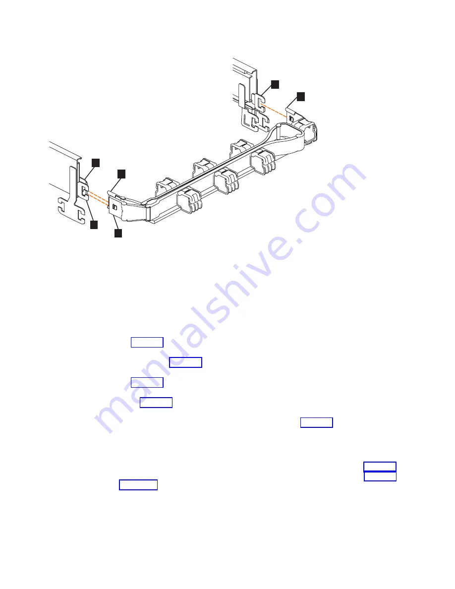
▌1▐
Inner connector on the upper CMA
▌2▐
Connector base on inner rail member
▌3▐
Outer connector on the upper CMA
▌4▐
Connector base on outer rail member
▌5▐
Support rail connector on the upper CMA
▌6▐
Connector base on outer rail member
1.
Press the latch on the connector base on the upper CMA assembly (
▌5▐
in
2.
Pull the connector to remove it from the connector base on the right support
rail (
▌6▐
3.
Press the latch on the outer connector of the upper CMA assembly (
▌3▐
in
4.
Remove the outer connector from the inner member of the left support rail (
▌4▐
in Figure 45).
5.
Remove the inner connector of the upper CMA assembly (
▌1▐
) from the inner
member of the left support rail (
▌2▐
), as shown in Figure 45.
Remove the lower CMA assembly
Note:
The procedure for removing the lower CMA assembly is the same as the
procedure to remove the upper CMA assembly. However, the connector locations
are reversed. For example, the connector base of the upper CMA (
▌5▐
connects to the right rail. The connector base of the lower CMA (
▌11▐
on page 61) attaches to the left rail.
svc01035
1
2
3
4
5
6
Figure 45. Connectors for the upper cable management arm
60
Storwize V7000 Gen2 and Gen2+: Quick Installation Guide
Summary of Contents for StorVize V7000 Gen2
Page 8: ...viii Storwize V7000 Gen2 and Gen2 Quick Installation Guide ...
Page 24: ...xxiv Storwize V7000 Gen2 and Gen2 Quick Installation Guide ...
Page 36: ...12 Storwize V7000 Gen2 and Gen2 Quick Installation Guide ...
Page 166: ...142 Storwize V7000 Gen2 and Gen2 Quick Installation Guide ...
Page 174: ...150 Storwize V7000 Gen2 and Gen2 Quick Installation Guide ...
Page 176: ...152 Storwize V7000 Gen2 and Gen2 Quick Installation Guide ...
Page 184: ...160 Storwize V7000 Gen2 and Gen2 Quick Installation Guide ...
Page 187: ......
Page 188: ...IBM Printed in USA GC27 6500 08 ...


