


b.
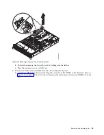
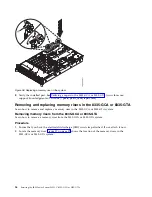
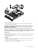
Grasp the memory DIMM along its edges and align it with the slot on the riser.
Attention:
Memory is keyed to prevent it from being installed incorrectly. Note the location of
the key tab within the memory connector before you attempt to install it.
c.
Press firmly on each side of the memory DIMM until the locking tab locks in place with an
audible click.
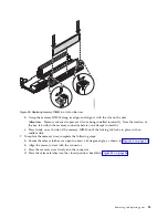
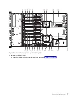
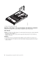
7.
To replace the memory riser, complete the following steps:
a.
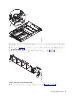
Ensure the release latches are open to about a 60 degree angle, as shown in Figure 36 on page 36.
b.
Align the memory riser with the connector.
c.
Press the memory riser firmly into the connector.
d.
Press the release latches into the closed position. See (A) in Figure 36 on page 36.
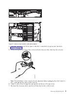
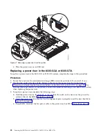
Figure 35. Replacing memory DIMM in a slot on the riser
Removing and replacing parts
35
Summary of Contents for S822LC
Page 1: ...Power Systems Servicing the IBM Power System S822LC 8335 GCA or 8335 GTA IBM...
Page 2: ......
Page 3: ...Power Systems Servicing the IBM Power System S822LC 8335 GCA or 8335 GTA IBM...
Page 16: ...xiv Servicing the IBM Power System S822LC 8335 GCA or 8335 GTA...
Page 134: ...118 Servicing the IBM Power System S822LC 8335 GCA or 8335 GTA...
Page 145: ...Notices 129...
Page 146: ...IBM Printed in USA...


