10. Connect appropriate cables to the adapter.
11. Install the covers that you removed earlier, and return the drawer to the normal
operating position.
12. Plug in the system unit power cables.
13. Turn on the power.
Installing a Hot-Pluggable PCI Adapter
Note: If you have more than one I/O drawer, determine into which drawer you will
install the adapter. Note the drawer number if displayed on the I/O drawer
operator panel.
To install the adapter, perform the following steps:
1. Place the I/O drawer in the rear service position:
a. If you have not already done so, open the front door of the rack unit.
b. Loosen the two thumbscrews that attach the front bezel to the drawer.
c. Grasp both sides of the front bezel and pull the bezel off the drawer.
d. If you have not already done so, open the rear door of the rack unit.
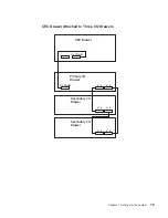
e. If present, remove the two retaining screws at the rear of the drawer. See the
figure on page 10.
f. Grasp the bar at the rear of the drawer, and pull the drawer to the rear until it is
stopped by the two detents on the top of the drawer.
Note: Make sure that you do not damage the cables while pulling out the drawer.
2. Remove the two thumbscrews, and remove the top cover from the drawer.
3. Refer to “PCI Hot-Plug Manager Access” on page 37, and follow the steps in the
access procedure to select PCI Hot Plug Manager. Then return here to continue.
4. From the PCI Hot-Plug Manager menu, select Add a PCI Hot-Plug Adapter and,
then press Enter. The Add a Hot-Plug Adapter window displays.
5. See the
PCI Adapter Placement Reference, order number SA38-0538, for adapter
placement information. Then select an empty PCI slot for the adapter. If you noted
the drawer’s number, use it to select the slot in the appropriate drawer.
6. Select the appropriate empty PCI slot from the ones listed on the screen, and
press Enter.
7. Turn the locking latch, lift the plastic stop, and remove the blank slot cover.
8. Follow the instructions on the screen to install the adapter until the visual indicator
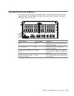
(LED) for the specified PCI slot is set to the action state. See “I/O Drawer PCI Slot
LED Definitions” on page 29.
9. When you are instructed to install the adapter in the adapter slot, carefully grasp
the adapter by the edges and align the adapter in the slot guides. Insert the
adapter fully into the adapter slot connector. If you are installing a full-length
adapter, ensure that both ends of the adapter engage the card guides.
32
Installation Guide
Summary of Contents for RS/6000 Enterprise Server M80
Page 6: ...vi Installation Guide...
Page 10: ...x Installation Guide...
Page 12: ...xii Installation Guide...
Page 54: ...40 Installation Guide...
Page 66: ...52 Installation Guide...
Page 70: ...56 Installation Guide...
Page 72: ...58 Installation Guide...
Page 74: ...60 Installation Guide...
Page 82: ...68 Installation Guide...
Page 93: ......
Page 94: ...IBMR Part Number 09P4388 Printed in U S A September 2001 SA38 0576 02 1P P N 09P4388...


