


P7EEL500-2
2.
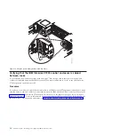
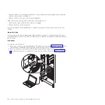
Position the rack where you want it to be installed.
3.
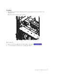
Use the open-end wrench that comes with the hardware kit to lower each of the four leveling pads
just enough so that they touch the floor. The rack casters support the weight of the rack cabinet. The
pads prevent the rack from rolling.
4.
Ensure that the power cords are securely attached to each power distribution unit (PDU).
5.
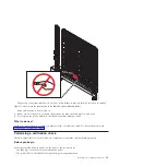
Install the front, back, and side covers onto the system.
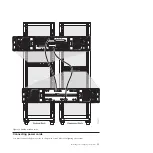
6.
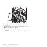
Install the recirculation prevention plate and the front stabilizer bracket on the front of the rack
cabinet. The recirculation prevention plate uses the same four screws and holes in the rack as the
front stabilizer bracket.
a.
Align the four holes in the recirculation prevention plate with the four holes in the rack cabinet.
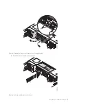
b.
Position the front stabilizer bracket in front of the recirculation prevention plate and align the
screw holes.
c.
Use the four screws and the hex wrench that come in the hardware kit to secure the front
stabilizer bracket and recirculation prevention plate (also referred to as the
air baffle
) to the rack
cabinet.
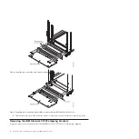
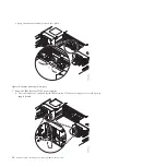
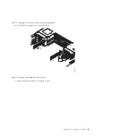
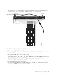
Figure 3. Removing the outriggers
Installing and configuring the system
5
Summary of Contents for PureFlex System
Page 1: ...PureFlex System Installing and configuring IBM PureFlex System GI11 9880 02...
Page 2: ......
Page 3: ...PureFlex System Installing and configuring IBM PureFlex System GI11 9880 02...
Page 6: ...iv PureFlex System Installing and configuring IBM PureFlex System...
Page 34: ...22 PureFlex System Installing and configuring IBM PureFlex System...
Page 44: ...32 PureFlex System Installing and configuring IBM PureFlex System...
Page 45: ......
Page 46: ...Part Number 00L5196 Printed in USA GI11 9880 02 1P P N 00L5196...


