background image

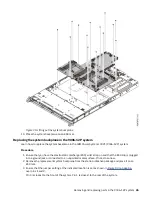
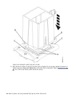
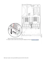
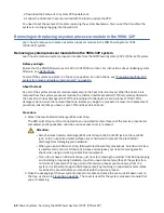
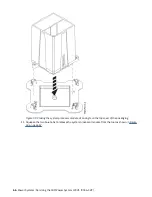
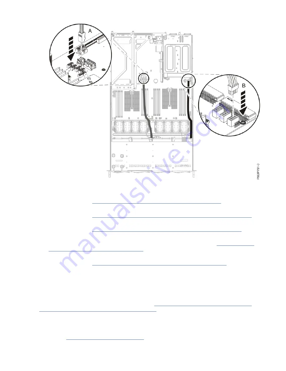
Figure 53. Replacing the cover switch cable

23. Replace all the fans and housings in the system.

For instructions, see “Replacing a system fan in the 9006-12P system” on page 22.

24. Transfer the TPM card from the old system backplane to the new system backplane.

For instructions, see “Removing and replacing the TPM card in the 9006-12P system” on page 77.

25. Transfer the memory DIMMs from the old system backplane to the new system backplane.

For instructions, see “Removing and replacing memory in the 9006-12P system” on page 25.

26. Replace both PCIe risers.

Using your labels, connect the cables to the PCIe adapters. For instructions, see “Replacing a PCIe

adapter in the 9006-12P system” on page 32. Replace the PCIe riser next to the power supply first.

27. Replace the power supplies.

For instructions, see “Replacing a power supply in the 9006-12P system” on page 38.

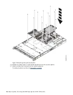
28. Install the processor air baffle.

Insert the edge of the air baffle into the fan support. Then, carefully press the air baffle down into

place.

What to do next
Prepare the system for operation. For instructions, see “Preparing the 9006-12P system for operation

after you remove and replace internal parts” on page 89.
After you replace the system backplane, you must set the system serial number and model number in the

system backplane by using the vital product data (VPD) update tool. To download the tool, complete the

following steps:

1. Go to the Scale-out LC system VPD update tool website (www-304.ibm.com/support/

customercare/sas/f/lopdiags/scaleOutLCdebugtool.html).

Removing and replacing parts in the 9006-12P system  59

Summary of Contents for Power System LC921 9006-12P

Page 1: ...Power Systems Servicing the IBM Power System LC921 9006 12P IBM...

Page 2: ...G229 9054 and the IBM Environmental Notices and User Guide Z125 5823 This edition applies to IBM Power Systems servers that contain the POWER9 processor and to all associated models Copyright Interna...

Page 3: ...module 67 Time of day battery 75 TPM card 77 Common procedures for servicing or installing features in the 9006 12P 81 Before you begin servicing 81 Identifying the 5104 22C 9006 12P 9006 22C or 9006...

Page 4: ...12P 102 Disconnecting the power cords 102 Connecting the power cords 103 Additional information 105 Drive installation options for the 9006 12P system 105 Notices 107 Accessibility features for IBM P...

Page 5: ...00 300 8751 German safety information Das Produkt ist nicht f r den Einsatz an Bildschirmarbeitspl tzen im Sinne 2 der Bildschirmarbeitsverordnung geeignet Laser safety information IBM servers can use...

Page 6: ...nect 1 Turn off everything unless instructed otherwise 2 For AC power remove the power cords from the outlets 3 For racks with a DC power distribution panel PDP turn off the circuit breakers located i...

Page 7: ...devices that attach to the system It is the responsibility of the customer to ensure that the outlet is correctly wired and grounded to prevent an electrical shock R001 part 1 of 2 R001 part 2 of 2 CA...

Page 8: ...that the route that you choose can support the weight of the loaded rack cabinet Refer to the documentation that comes with your rack cabinet for the weight of a loaded rack cabinet Verify that all d...

Page 9: ...position for example when working from a ladder Stability hazard The rack may tip over causing serious personal injury Before extending the rack to the installation position read the installation ins...

Page 10: ...e equipped with multiple AC power cords or multiple DC power cables To remove all hazardous voltages disconnect all power cords and power cables L003 L007 CAUTION A hot surface nearby L007 x Power Sys...

Page 11: ...ing into the other end of a disconnected optical fiber to verify the continuity of optic fibers may not injure the eye this procedure is potentially dangerous Therefore verifying the continuity of opt...

Page 12: ...th platforms without appreciable force so take care not to push or lean Keep riser tilt adjustable angling platform option flat at all times except for final minor angle adjustment when needed Do not...

Page 13: ...itable for connection to intrabuilding or unexposed wiring or cabling only The intrabuilding ports of this equipment must not be metallically connected to the interfaces that connect to the OSP outsid...

Page 14: ...xiv Power Systems Servicing the IBM Power System LC921 9006 12P...

Page 15: ...that you have access to a medium flat blade screwdriver and a Phillips screwdriver 5 If parts are incorrect missing or visibly damaged contact the provider of the part or your next level of support D...

Page 16: ...DC power source 4 Remove the signal cables from the connectors 5 Remove all cables from the devices To Connect 1 Turn off everything unless instructed otherwise 2 Attach all cables to the devices 3 At...

Page 17: ...control It does not increase or decrease your risk of receiving electric shock when using or working on electrical equipment If you do not have an ESD wrist strap just prior to removing the product fr...

Page 18: ...the drive as you slide it out of the system Do not hold the drive by the handle 5 If the drive does not match the serial number you wrote down in a previous step reinstall the drive in the bay you re...

Page 19: ...e tray a Turn the tray upside down as shown in Figure 3 on page 6 b Open the retention spring A as shown in Figure 4 on page 7 c Lift the 2 5 inch drive B out of the tray d Close the retention spring...

Page 20: ...Figure 3 Turning the 2 5 inch tray upside down 6 Power Systems Servicing the IBM Power System LC921 9006 12P...

Page 21: ...edure 1 Ensure that you have the electrostatic discharge ESD wrist strap on and that the ESD clip is plugged into a ground jack or connected to an unpainted metal surface If not do so now 2 Install a...

Page 22: ...6 on page 9 b Open the retention spring B as shown in Figure 7 on page 10 c Place the 2 5 inch drive A into the tray aligning the pins with the screw holes in the drive d When the pins are aligned clo...

Page 23: ...Figure 6 Turning the 2 5 inch tray upside down Removing and replacing parts in the 9006 12P system 9...

Page 24: ...ttom as you position the drive and insert it into the drive slot Ensure that the drive is fully seated and is all the way into the system 4 Lock the drive bay handle A by pushing in the handle release...

Page 25: ...i bus command in the Ubuntu Linux operating system log in to the system as the root user and run the following command rescan scsi bus The rescan scsi bus tool is available in the scsitools package in...

Page 26: ...ace until the service procedure is completed and if applicable until the service access cover is replaced Attention Attach an electrostatic discharge ESD wrist strap to the front ESD jack to the rear...

Page 27: ...rts on page 86 Procedure 1 Attach the electrostatic discharge ESD wrist strap The ESD wrist strap must be connected to an unpainted metal surface until the service procedure is completed and if applic...

Page 28: ...for at least 5 seconds before you continue with the service process 2 Install the DOM into the system backplane in positions A as shown in Figure 10 on page 14 Depending on the DOM model you might als...

Page 29: ...the IBM Power System LC921 9006 12P system About this task You can use a commercially available magnetic tip screwdriver to remove and replace the screws Removing the disk drive backplane from the 90...

Page 30: ...em on page 19 4 Partially remove the front drive trays You do not need to completely remove the drives pull them out about 2 cm 1 in For instructions see Removing a front disk drive from the 9006 12P...

Page 31: ...o so now 2 Remove the replacement disk drive backplane and cables from the protective plastic envelope 3 Replace the disk drive backplane as shown in Figure 12 on page 18 a Insert the disk drive backp...

Page 32: ...the system processor air baffles Insert the edge of the air baffle into the fan support Then carefully press the air baffle down into place What to do next Prepare the system for operation For instru...

Page 33: ...hardware to prevent the electrostatic discharge from damaging your hardware When you use an ESD wrist strap follow all electrical safety procedures An ESD wrist strap is used for static control It do...

Page 34: ...Figure 13 Removing the fan holder 3 Push the fan up from the holder as shown in Figure 14 on page 21 20 Power Systems Servicing the IBM Power System LC921 9006 12P...

Page 35: ...able release the connector clip B and carefully pull up the connector A from the system backplane as shown in Figure 15 on page 22 Do not pull on the wires Feed the cable through the fan holder Removi...

Page 36: ...ou have the electrostatic discharge ESD wrist strap on and that the ESD clip is plugged into a ground jack or connected to an unpainted metal surface If not do so now 2 With the fan holder lifted push...

Page 37: ...he pins at the bottom of the chassis as shown in Figure 17 on page 24 For the fan holder near the cover switch temporarily move the cover switch wires out of the way When the fan holder is seated into...

Page 38: ...Figure 17 Aligning the fan holder 4 Connect the fan cable to the system backplane as shown in Figure 18 on page 25 24 Power Systems Servicing the IBM Power System LC921 9006 12P...

Page 39: ...replacing memory in the 9006 12P system Learn how to remove and replace memory in the IBM Power System LC921 9006 12P system Before you begin Power off the system and place it in the service position...

Page 40: ...conds If at any point in this service process you move away from the system it is important to again discharge yourself by touching an unpainted metal surface for at least 5 seconds before you continu...

Page 41: ...tion Memory is keyed to prevent it from being installed incorrectly Note the location of the key tab within the memory connector before you attempt to install it b Press firmly on each side of the mem...

Page 42: ...Then carefully press the air baffle down into place What to do next Prepare the system for operation For instructions see Preparing the 9006 12P system for operation after you remove and replace inte...

Page 43: ...SD packaging and installing or replacing hardware touch an unpainted metal surface of the system for a minimum of 5 seconds If at any point in this service process you move away from the system it is...

Page 44: ...itions 2 3 or 4 you must remove the PCIe cage and riser a Remove the PCIe riser as shown in Figure 23 on page 31 1 Retract the retaining pins A such that the arrows on the tabs point to the system 2 L...

Page 45: ...ESD surface 6 Remove the PCIe adapter A to be replaced from the PCIe riser B as shown in Figure 24 on page 31 or Figure 25 on page 32 a Remove the screw that secures the PCIe adapter to the PCIe riser...

Page 46: ...Removing the PCIe riser cards from the PCIe adapter cage Replacing a PCIe adapter in the 9006 12P system Learn how to replace a PCIe adapter in the IBM Power System LC921 9006 12P system Procedure 1 E...

Page 47: ...ing information c If needed install a support bracket for the PCIe adapter to the system backplane Also install a special support tailstock to the PCIe adapter d Insert the PCIe adapter into the PCIe...

Page 48: ...screws 5 If you need to replace the PCIe riser card A or B replace the screws that secure the PCIe riser card to the PCIe riser support C as shown in Figure 29 on page 35 34 Power Systems Servicing t...

Page 49: ...owing steps a Insert the PCIe adapter A into the PCIe riser B as shown in Figure 30 on page 35 or Figure 31 on page 36 aligning it properly and inserting it fully into the slot Secure the PCIe adapter...

Page 50: ...the PCIe adapter riser and the PCIe adapters it contains into the system backplane as shown in the following figure 1 Ensure that the PCIe holder release pins B are retracted such that the arrows poi...

Page 51: ...y failed it can be replaced while the system is running Procedure 1 Attach the electrostatic discharge ESD wrist strap The ESD wrist strap must be connected to an unpainted metal surface until the ser...

Page 52: ...ower supply from the system a To unseat the power supply from its position in the system push the locking tab to the left as shown in Figure 33 on page 38 b Grasp the power supply handle with one hand...

Page 53: ...and replace the system backplane in the IBM Power System LC921 9006 12P system About this task You can use a commercially available magnetic tip screwdriver to remove and replace the screws Removing t...

Page 54: ...st strap follow all electrical safety procedures An ESD wrist strap is used for static control It does not increase or decrease your risk of receiving electric shock when using or working on electrica...

Page 55: ...the system backplane For instructions see Removing the disk drive backplane from the 9006 12P system on page 15 Carefully pull them through the fan bulkhead to the front of the system 8 Remove the ope...

Page 56: ...or panel cable 9 Note the position and orientation of the cover switch cable Remove the cover switch cable from the system backplane as shown in Figure 37 on page 43 42 Power Systems Servicing the IBM...

Page 57: ...Figure 37 Removing the cover switch cable 10 Remove the 14 screws from the system backplane The screw locations are shown in Figure 38 on page 44 Removing and replacing parts in the 9006 12P system 43...

Page 58: ...backplane that is near the power supplies Save the plastic cover 12 Holding the processor heat sink carefully move the system backplane slightly forwards and up to remove it See Figure 39 on page 45...

Page 59: ...D wrist strap on and that the ESD clip is plugged into a ground jack or connected to an unpainted metal surface If not do so now 2 Remove the replacement system backplane from the static protective pa...

Page 60: ...ckplane to the new system backplane 4 Loosen the load arm screw A of the system processor heat sink B that you are removing by using a 3 Phillips screw driver The load arm pivots up in the direction t...

Page 61: ...igure 41 Loosening the load arm screw of the heat sink 5 Grip the heat sink and remove it by lifting straight up as shown in Figure 42 on page 48 Removing and replacing parts in the 9006 12P system 47...

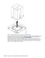
Page 62: ...a can of compressed air 9 With the removal tool A sitting on top of the system processor module push down on the tool to lock the system processor module into the tool as shown in Figure 43 on page 4...

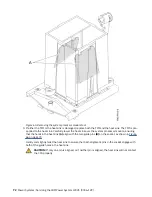
Page 63: ...e socket as shown in Figure 44 on page 50 Ensure that the two guide pins C are inserted into the alignment holes B on each side of the tool Use care to lower the tool evenly without tilting the tool D...

Page 64: ...ssor module holes and guide pins are properly aligned squeeze and hold the two blue release tabs A together until a firm stop is reached as shown in Figure 45 on page 51 Then lift the tool off the sys...

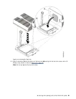
Page 65: ...circular the other alignment pin is an oval The oval shaped pin is towards the front of the system Ensure that the alignment holes A in the heat sink match the circular and oval alignment pins Carefu...

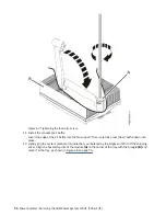
Page 66: ...load arm A into position over the heat sink B and tighten the load arm screw with a 3 Phillips screw driver as shown in Figure 47 on page 53 Note Do not overtighten the load arm screw 52 Power Systems...

Page 67: ...continue installing components into the new system backplane 15 Holding the processor heat sink carefully lower the system backplane into the chassis then slide it slightly back See Figure 48 on page...

Page 68: ...ce the plastic cover on system backplane that is near the power supplies 17 Align and screw the 14 screws into the system backplane The screw locations are shown in Figure 49 on page 55 54 Power Syste...

Page 69: ...placing the disk drive backplane in the 9006 12P system on page 17 19 Replace the operator panel cable into the system backplane as shown in Figure 50 on page 56 As you face the front of the system th...

Page 70: ...Figure 50 Replacing the operator panel cable 20 Replace the cover switch cable into the system backplane as shown in Figure 51 on page 57 56 Power Systems Servicing the IBM Power System LC921 9006 12P...

Page 71: ...below the chassis that support the processor sockets a Turn the system over upside down b Replace the screws from the bottom The screw locations are shown in Figure 52 on page 58 c Turn the system ov...

Page 72: ...lly route disk drive signal cable A and power cable B through the fan bulkhead to over the system backplane area Replace the disk drive signal and power cables into the system backplane as shown in Fi...

Page 73: ...2 Replace the PCIe riser next to the power supply first 27 Replace the power supplies For instructions see Replacing a power supply in the 9006 12P system on page 38 28 Install the processor air baffl...

Page 74: ...ssor removal and replacement procedure ensure that you have a spare TIM and heat sink on hand Procedure 1 Attach the electrostatic discharge ESD wrist strap The ESD wrist strap must be connected to an...

Page 75: ...and lift the processor air baffle from the system 4 Loosen the load arm screw A of the system processor heat sink B that you are removing by using a 3 Phillips screw driver The load arm pivots up in...

Page 76: ...e 55 Loosening the load arm screw of the heat sink 5 Grip the heat sink and remove it by lifting straight up as shown in Figure 56 on page 63 62 Power Systems Servicing the IBM Power System LC921 9006...

Page 77: ...st or debris use a can of compressed air 8 Align the tool with the beveled edge A of the system processor module as shown in Figure 57 on page 64 Lower the tool over the system processor module by ens...

Page 78: ...or module into the tool as shown in Figure 58 on page 65 The tool drops slightly when you push down on the system processor module so that the jaws can grab the bottom of the module Make sure that bot...

Page 79: ...t an angle on the top cover of the system processor module packaging as shown in Figure 59 on page 66 Setting the system processor module at an angle on the top cover of the system processor module pa...

Page 80: ...sor module at an angle on the top cover of the packaging 11 Squeeze the two blue tabs to release the system processor module from the tool as shown in Figure 60 on page 67 66 Power Systems Servicing t...

Page 81: ...nd that the ESD clip is plugged into a ground jack or connected to an unpainted metal surface If not do so now 2 Inspect the system processor socket area and remove any dust or debris use a can of com...

Page 82: ...e tool as shown in Figure 62 on page 69 The tool drops slightly when you push down on the system processor module so that the jaws can grab the bottom of the module Make sure that both of the tool jaw...

Page 83: ...tool 5 Inspect the system processor socket area and remove any dust or debris use a can of compressed air 6 Lift the system processor module from the packaging tray as shown in Figure 63 on page 70 R...

Page 84: ...are inserted into the alignment holes B on each side of the tool Use care to lower the tool evenly without tilting the tool Do not attempt to slide the tool and the system processor module in any dir...

Page 85: ...ocessor module holes and guide pins are properly aligned squeeze and hold the two blue release tabs A together until a firm stop is reached as shown in Figure 65 on page 72 Then lift the tool off the...

Page 86: ...e ensuring that the holes in the heat sink A align with the two guide pins B on the socket as shown in Figure 66 on page 73 Gently and slightly twist the heat sink to ensure that both alignment pins i...

Page 87: ...the load arm A into position over the heat sink B and tighten the load arm screw with a 3 Phillips screw driver as shown in Figure 67 on page 74 Note Do not overtighten the load arm screw Removing and...

Page 88: ...s the air baffle down into place 12 Lightly grip the system processor module that you replaced by the edges and lift it off the shipping cover Align the beveled corner of the module A to the corner of...

Page 89: ...m and place it in the service position For instructions see Preparing the 9006 12P system to remove and replace internal parts on page 86 Procedure 1 Attach the electrostatic discharge ESD wrist strap...

Page 90: ...to again discharge yourself by touching an unpainted metal surface for at least 5 seconds before you continue with the service process 2 If the time of day battery is covered by a PCIe adapter move th...

Page 91: ...ts on page 89 You need to set the system s time after replacing the battery You can set the time after the system is running by logging into the web GUI Removing and replacing the TPM card in the 9006...

Page 92: ...decrease your risk of receiving electric shock when using or working on electrical equipment If you do not have an ESD wrist strap just prior to removing the product from ESD packaging and installing...

Page 93: ...e TPM card must be plugged in properly Check the pins on the card and the holes in the card socket to properly orient the TMP card One of the TPM card socket holes is filled in the corresponding pin o...

Page 94: ...e Removing and replacing memory in the 9006 12P system on page 25 What to do next Prepare the system for operation For instructions see Preparing the 9006 12P system for operation after you remove and...

Page 95: ...t be equipped with multiple power cords To remove all hazardous voltages disconnect all power cords For AC power disconnect all power cords from their AC power source For racks with a DC power distrib...

Page 96: ...edges corners and joints may be present in and around the system Use care when handling equipment to avoid cuts scrapes and pinching D005 R001 part 1 of 2 DANGER Observe the following precautions whe...

Page 97: ...k refer to the rating labels located on the equipment in the rack to determine the total power requirement of the supply circuit For sliding drawers Do not pull out or install any drawer or feature if...

Page 98: ...lace Learn how to determine which system has the part you want to replace LEDs on the 9006 12P system Use this information as a guide to the LEDs on the IBM Power System LC921 9006 12P system The LEDs...

Page 99: ...n the rear of the system see Figure 74 on page 85 The identify LED is at 2 Turn it on by using a system identify command or by pressing the UID button Figure 74 LEDs on the rear of the system Common p...

Page 100: ...identify interval interface The interface that you are using to connect to the system For example usb interval The time to turn on the identify LED in seconds The default value is 15 This means that...

Page 101: ...painted metal surface of the system for a minimum of 5 seconds If at any point in this service process you move away from the system it is important to again discharge yourself by touching an unpainte...

Page 102: ...product might be equipped with multiple AC power cords or multiple DC power cables To remove all hazardous voltages disconnect all power cords and power cables L003 L005 88 Power Systems Servicing th...

Page 103: ...have the electrostatic discharge ESD wrist strap on and that the ESD clip is plugged into a ground jack or connected to an unpainted metal surface If not do so now 2 Replace the service access cover F...

Page 104: ...ow purposes and thermal performance the service access cover must be installed and fully seated before you power on the system You can use this procedure to power on the system or you can use a consol...

Page 105: ...mplete the steps in this procedure Procedure You can use the Linux shutdown command to stop and power down the system For example the following command will shut down the system in 10 minutes and send...

Page 106: ...e 1 device 0 11 ddd StorCLI commands Learn about the StorCLI commands They are for use with the PCIe adapter feature codes EKAA and EKEA If the command is not installed download the utility from Broad...

Page 107: ...I x xx x noarch rpm To show a summary of the drive and controller status storcli show To show a list of all controllers and drives that need attention storcli show all To show information about the dr...

Page 108: ...SAS HBA AOC S3008L L8i AOC S3008L L8i Tools To install 1 Download the sas3ircu command 2 Copy the sas3ircu command file to the usr local bin directory 3 To enable the command to be executed as root r...

Page 109: ...ew the sensor readings GUI display log in to the BMC web interface Click Server Health Sensor Readings Some occurrences of errors in the system might not appear in the sensor readings GUI After you vi...

Page 110: ...12P system Learn how to remove the service access cover from an IBM Power System LC921 9006 12P system About this task Attention For safety airflow purposes and thermal performance the service access...

Page 111: ...12P system About this task Attention For safety airflow purposes and thermal performance the service access cover must be installed and fully seated before you power on the system Procedure 1 Place th...

Page 112: ...ace an IBM Power System LC921 9006 12P system into the service or operating position Placing an 9006 12P system into the service position Learn how to place an IBM Power System LC921 9006 12P system i...

Page 113: ...rack from toppling Slide only one system out at a time When the rails are fully extended the rail safety latches lock into place This action prevents the system from being pulled out too far Procedur...

Page 114: ...remove it from the slide rails The chassis contains most of the weight in the back side of the unit When you remove the system take care to be ready to support the weight by grasping the chassis close...

Page 115: ...the rack rails 3 Push the system into the rack until you hear each rail click into place 4 Before releasing your hold on the system ensure that the rails are engaged by sliding the system forward int...

Page 116: ...om the 9006 12P system To disconnect the power cords from a system complete the steps in this procedure Before you begin Note This system might be equipped with two or more power supplies If the remov...

Page 117: ...onnect the power cords to a system complete the steps in this procedure Procedure Using your labels reconnect the power cords to the system unit as shown in Figure 82 on page 103 Figure 82 Connecting...

Page 118: ...104 Power Systems Servicing the IBM Power System LC921 9006 12P...

Page 119: ...adapter supporting four front mounted SATA SAS drives Two SATA DOMs plugged into the system backplane NVMe Enabled System and Drives When the system has an NVMe adapter the system supports NVMe drive...

Page 120: ...106 Power Systems Servicing the IBM Power System LC921 9006 12P...

Page 121: ...ct s and or the program s described in this publication at any time without notice Any references in this information to non IBM websites are provided for convenience only and do not in any manner ser...

Page 122: ...information technology content successfully Overview The IBM Power Systems servers include the following major accessibility features Keyboard only operation Operations that use a screen reader The IB...

Page 123: ...rovide you as the customer the ability to collect personally identifiable information from end users via cookies and other technologies you should seek your own legal advice about any laws applicable...

Page 124: ...ngen der EU Richtlinie 2014 30 EU zur Angleichung der Rechtsvorschriften ber die elektromagnetische Vertr glichkeit in den EU Mitgliedsstaatenund h lt die Grenzwerte der EN 55022 EN 55032 Klasse A ein...

Page 125: ...elle Informationen Das Ger t erf llt die Schutzanforderungen nach EN 55024 und EN 55022 EN 55032 Klasse A Japan Electronics and Information Technology Industries Association JEITA Notice This statemen...

Page 126: ...struction manual may cause harmful interference to radio communications Operation of this equipment in a residential area is likely to cause harmful interference in which case the user will be require...

Page 127: ...Richtlinie zur Elektromagnetischen Vertr glichkeit Dieses Produkt entspricht den Schutzanforderungen der EU Richtlinie 2014 30 EU zur Angleichung der Rechtsvorschriften ber die elektromagnetische Ver...

Page 128: ...55032 Klasse B Japan Electronics and Information Technology Industries Association JEITA Notice This statement applies to products less than or equal to 20 A per phase This statement applies to produc...

Page 129: ...or television interference caused by using other than recommended cables and connectors or by unauthorized changes or modifications to this equipment Unauthorized changes or modifications could void...

Page 130: ...ermined by IBM the above instructions are not being properly followed You may not download export or re export this information except in full compliance with all applicable laws and regulations inclu...

Page 131: ......

Page 132: ...IBM...

Reviews: