background image

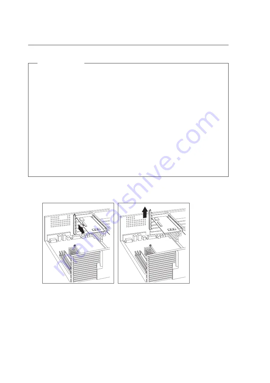
Removing Adapters from the Riser Card

Before you begin

Ÿ

Read “Electrical Safety” on page 4 and “Handling Static-Sensitive Devices”
on page 5.

Ÿ

Turn off the computer and all other connected devices.

Ÿ

Disconnect all cables attached to the computer (see “Disconnecting Cables
and Removing the Cover” on page 6).

Attention:

 The presence of 5 V standby power might result in damage to

your hardware unless you disconnect the power cord from the wall before
opening the computer.

Ÿ

Remove the computer cover, and lay the computer on its side (see
“Disconnecting Cables and Removing the Cover” on page 6).

Ÿ

To remove some adapters, you might need to remove the bottom cover, the
system board, and the fan. For more information, see “Opening the Bottom
Cover” on page 39, “Moving the System Board” on page 41, and “Moving
the Front Fan” on page 44.

1

Remove the screw and the bracket.

34

Installing Options in Your Personal Computer 


All manuals and user guides at all-guides.com

Summary of Contents for PC 300PL

Page 1: ...Personal Computer Installing Options in Your Personal Computer PC 300PL Type 6892 PC 300GL Type 6285 All manuals and user guides at all guides com a l l g u i d e s c o m...

Page 2: ...All manuals and user guides at all guides com...

Page 3: ...Personal Computer Installing Options in Your Personal Computer PC 300PL Type 6892 PC 300GL Type 6285 IBM All manuals and user guides at all guides com...

Page 4: ...n herein these changes will be incorporated in new editions of the publication IBM may make improvements and or changes in the product s and or the program s described in this publication at any time...

Page 5: ...t Connectors 11 Chapter 3 Working with Options on the System Board 12 Accessing the System Board 13 Identifying Parts on the System Board 13 Working with System Memory 14 Memory Configuration 15 Insta...

Page 6: ...Lost or Forgotten Passwords 73 Chapter 7 Completing the Installation 76 Replacing the Cover and Connecting the Cables 77 Updating the Computer Configuration 79 Starting the Configuration Setup Utility...

Page 7: ...K by law the power cord must be disconnected after the telephone line cable 2 In the U K by law the telephone cable must be connected after the power cord 1 2 1 Electrical current from power telephone...

Page 8: ...for Class 1 laser products When a CD ROM drive is installed note the following CAUTION Use of controls or adjustments or performance of procedures other than those specified herein might result in haz...

Page 9: ...ry as required by local ordinances or regulations ATTENTION Danger d explosion en cas de remplacement incorrect de la batterie Remplacer uniquement par une batterie IBM de type 33F8354 ou d un type qu...

Page 10: ...ost options Also this book contains information that will help you decide which options to add to your computer This publication provides information for the PC 300PL and the PC 300GL Some illustratio...

Page 11: ...Chapter 6 Working with Security Options describes features such as the security U bolt and erasing lost or forgotten passwords Chapter 7 Completing the Installation provides instructions for reassemb...

Page 12: ...ut Your Software This publication provided only with computers that have IBM preinstalled software contains information about the preinstalled software package Your Ready to Configure Utility Program...

Page 13: ...is publication contains more information about the technical aspects of your computer It is available on the World Wide Web at http www pc ibm com us cdt treport html About This Book xi All manuals an...

Page 14: ...xii Installing Options in Your Personal Computer All manuals and user guides at all guides com...

Page 15: ...atures that are available for your computer Also important information about required tools electrical safety and static sensitive devices is included Important Before you install or remove any option...

Page 16: ...ng are some other available options and features for your computer For more information refer to the documentation that comes with the optional hardware If your computer does not have an Ethernet conn...

Page 17: ...wnload device drivers and updates Some of these pages are http www ibm com Main IBM home page http www pc ibm com IBM Personal Computer home page http www pc ibm com us cdt IBM Commercial Desktop home...

Page 18: ...Personal computer users in the United Kingdom who have a modem or fax machine attached to their computer must disconnect the telephone line from the computer before unplugging any power cords also kno...

Page 19: ...le components carefully Handle adapters and memory modules by the edges Never touch any exposed circuitry Prevent others from touching components When you are installing a new option touch the static...

Page 20: ...et on the bottom of the cover are hanging over the edge of the table so that they don t break 1 Unplug all power cords from electrical outlets If you have a modem or fax machine attached to your compu...

Page 21: ...e rear of the computer on some models Cover Lock Attention If your computer is a PC 300PL model and you have set an administrator password read the important information in Appendix A PC 300PL Asset S...

Page 22: ...ver toward the front of the computer Lift the cover off Cover Release Tab Important When you need to access the inside of the computer you should allow the feet to hang off the edge of the table so th...

Page 23: ...For information on removing the cover see Disconnecting Cables and Removing the Cover on page 6 Note The following illustration is for reference only Your computer might differ from the one shown 1 D...

Page 24: ...CD ROM eject button 7 CD ROM emergency eject 8 Bay 2 9 Bay 3 1 Bay 4 3 5 diskette drive S o c k e t 7 S o c k e t 7 Your computer comes with a diskette drive installed in bay 4 and a hard disk drive i...

Page 25: ...ovides access to the I O connectors Adapters installed in expansion slots might also provide I O connectors 2 2 1 1 Monitor USB 2 Parallel Line In Microphone PL Models Only Ethernet Line Out Keyboard...

Page 26: ...omputer configuration before installing an optional device This allows you to view and compare the changes in the computer configuration after you install an option Also if you have problems configuri...

Page 27: ...ard in your computer It provides basic computer functions and supports a variety of devices that are IBM installed or that you can install later If you plan to install remove or replace hardware in yo...

Page 28: ...DIMM 2 The memory modules your computer uses are dual inline memory modules DIMMs The IBM installed DIMMs that come with your computer are non parity or ECC error checking and correction 100 MHz SDRAM...

Page 29: ...computer this table and additional information are also found on a label inside the computer Note Values in the following table are represented in megabytes MB Total Memory MB DIMM 0 DIMM 1 DIMM 2 16...

Page 30: ...ting Cables and Removing the Cover on page 6 and lay the computer on its side Note For information on memory configuration see the table on page 15 1 To locate the memory connectors inside your comput...

Page 31: ...d both ends of the module 6 To install another memory module repeat steps 1 5 7 Go to the device record form in Using Your Personal Computer and record this installation What to do next To work with a...

Page 32: ...re opening the computer cover Remove the computer cover see Disconnecting Cables and Removing the Cover on page 6 and lay the computer on its side 1 To locate the memory connectors inside your compute...

Page 33: ...to do next To work with another option go to the appropriate section To complete the installation go to Chapter 7 Completing the Installation on page 76 Chapter 3 Working with Options on the System B...

Page 34: ...that come with the optional device Turn off the computer and all other connected devices Disconnect all cables attached to the computer Attention The presence of 5 V standby power might result in dama...

Page 35: ...by the two clips What to do next To work with another option go to the appropriate section To complete the installation go to Chapter 7 Completing the Installation on page 76 Chapter 3 Working with Op...

Page 36: ...ter has been running To avoid the possibility of a burn if the computer has been on let the microprocessor and heat sink cool for 10 minutes before continuing with the procedure Before you begin Read...

Page 37: ...ll tabs on the top of the microprocessor Push in toward the microprocessor until the tabs release Tabs 3 Carefully place one hand on the computer frame and with the other hand pull the microprocessor...

Page 38: ...the computer and then remove the new microprocessor 6 Press in on the retainer tabs until they click into place 7 Align the new microprocessor with the connector on the system board and slide it into...

Page 39: ...itches see Identifying Parts on the System Board on page 13 For information on the appropriate switch settings see the label on the underside of the computer cover or contact your place of purchase or...

Page 40: ...required resources are available Refer to the instructions that come with your adapter to determine if it is Plug and Play For more information see Adapter Configuration on page 29 Important Run Conf...

Page 41: ...ector SCSI Hard Disk LED Wake on LAN Alert on LAN Asset ID Antenna Chassis Intrusion Detector Internal Speaker CD Audio Notes 1 Chassis intrusion Alert on LAN and Asset ID are available on some models...

Page 42: ...card When installing optional drives refer to the following illustration for the location of the appropriate connectors LED Panel Primary IDE Secondary IDE Diskette Drive Power 28 Installing Options i...

Page 43: ...puter during startup When you install or remove Plug and Play adapters this information is interpreted by the basic input output system BIOS which supports Plug and Play technology If the required res...

Page 44: ...e resources for the legacy adapter and prevents the BIOS from using these resources for the system or other Plug and Play adapters Just as you change system resources when you install an ISA legacy ad...

Page 45: ...ention The presence of 5 V standby power might result in damage to your hardware unless you disconnect the power cord from the wall before opening the computer Remove the computer cover and lay the co...

Page 46: ...er face up Expansion Slot Cover Adapter Card Riser Card 3 Install the bracket and the screw 4 If you installed a network adapter that uses Wake on LAN or Alert on LAN attach the cable from the riser c...

Page 47: ...er the fan or the system board replace them See Moving the Front Fan on page 44 Moving the System Board on page 41 and Opening the Bottom Cover on page 39 To work with another option go to the appropr...

Page 48: ...your hardware unless you disconnect the power cord from the wall before opening the computer Remove the computer cover and lay the computer on its side see Disconnecting Cables and Removing the Cover...

Page 49: ...ver Adapter Card Riser Card 3 Install the bracket and the screw Note Removing an adapter frees up system resources If you remove an ISA legacy adapter you must use the Configuration Setup Utility prog...

Page 50: ...ystem board replace them See Moving the Front Fan on page 44 Moving the System Board on page 41 and Opening the Bottom Cover on page 39 To work with another option go to the appropriate section To com...

Page 51: ...es attached to the computer Attention The presence of 5 V standby power might result in damage to your hardware unless you disconnect the power cord from the wall before opening the computer cover Rem...

Page 52: ...hter card might provide another connector for external devices a second slot is provided on the computer wall for access What to do next Go to the device record form in Using Your Personal Computer an...

Page 53: ...resence of 5 V standby power might result in damage to your hardware unless you disconnect the power cord from the wall before opening the computer cover Remove the computer cover see Disconnecting Ca...

Page 54: ...gn the tabs on the end with the openings in the frame 2 Fit the tabs into the openings and pivot the bottom cover until it is closed 3 Align the holes and insert the two screws 40 Installing Options i...

Page 55: ...cover Remove the computer cover see Disconnecting Cables and Removing the Cover on page 6 and lay the computer on its side Remove the bottom cover see Opening the Bottom Cover on page 39 To remove th...

Page 56: ...Grasp the rails and slide the board in until it is approximately 6 mm 0 25 in from the riser card edge connector 3 Rotate the latch handle counter clockwise until the system board is properly aligned...

Page 57: ...nto the opening in the chassis This holds the latch in the latched position Tab Push Here System Board Tab Hole Note You cannot see the connection with a full sized adapter in place To make sure the s...

Page 58: ...m the wall before opening the computer cover Remove the computer cover see Disconnecting Cables and Removing the Cover on page 6 and lay the computer on its side Note You might have to remove the bott...

Page 59: ...fan assembly with the slots on the computer wall Next insert the tab on the fan assembly into the slot on the computer wall 4 Connect the fan cable to the connector on the riser card Chapter 4 Workin...

Page 60: ...ke a snapshot of your computer configuration before installing an optional device This allows you to view and compare the changes in the computer configuration after you install an option Also if you...

Page 61: ...as bay 1 bay 2 and so on Drive bays 1 through 4 at the front of your computer are contained in one drive cage and drive bays 5 and 6 at the back of your computer are contained in another Your compute...

Page 62: ...5 4 1 0 4 3 5 inch diskette drive 25 4 1 0 5 Hard disk drive 25 4 1 0 25 4 1 0 6 Hard disk drive 25 4 1 0 25 4 1 0 Notes You cannot install drives that are greater than 41 3 mm 1 6 in high You must in...

Page 63: ...important points to remember when connecting power and signal cables to internal drives The diskette drive and hard disk drive that are preinstalled in your computer come with power and signal cables...

Page 64: ...l signal cable The cable must meet the following specifications Maximum length 0 46 meters 18 inches Wire size 28 AWG Cable capacitive loading 200 pF maximum You can install one diskette drive only 50...

Page 65: ...e drive support bracket is present you must remove the drive cage before installing or removing drives see Removable Drive Cage Instructions on page 52 The following illustration shows a computer with...

Page 66: ...iven over the following pages Before you begin Read Electrical Safety on page 4 and Handling Static Sensitive Devices on page 5 Read the instructions that come with the drive you want to install or re...

Page 67: ...or removing drives you might find it easier to lay the computer on its side 1 Remove the Drive Cage a Disconnect any cables connected to drives 1 through 4 b Remove the top handle cover and set it asi...

Page 68: ...7 2 Install or Remove the Drive To install a drive a Remove the metal shield for the drive bay you want to use by pulling out the tabs on the sides of the shield until it flexes Lift off one side the...

Page 69: ...ing illustration shows a CD ROM drive being installed in bay 1 To remove a drive a Remove the screws holding the drive in place then slide the drive out of the bay b Place the removed drive in a stati...

Page 70: ...front of the computer be sure the holes for the screws in the drive cage and support bracket are aligned b Insert and tighten the screw anchoring the drive cage at the side then insert and tighten the...

Page 71: ...ables to the drives If necessary refer to page 28 for an illustration showing the locations of the drive connectors on the riser card Chapter 5 Working with Internal Drives 57 All manuals and user gui...

Page 72: ...a bay panel If you have installed a drive with removable media you must remove the bay panel Use the tip of a screwdriver to release the bay panel 58 Installing Options in Your Personal Computer All...

Page 73: ...t to do next If you installed a CD ROM drive and want to connect the drive to the CD ROM audio connector see page 27 to locate the CD ROM audio connector on the riser card Go to the device record form...

Page 74: ...in Read Electrical Safety on page 4 and Handling Static Sensitive Devices on page 5 Turn off the computer and all other connected devices Disconnect all cables attached to the computer Attention The p...

Page 75: ...t find it easier to lay the computer on its side Installing a Drive 1 Use the tip of a screwdriver to remove the bay panel for the appropriate drive bay The following illustration shows a bay panel be...

Page 76: ...iver or pliers to remove The following illustration shows the type of knockouts in bay 1 The following illustration shows the type of knockout in bays 2 and 3 62 Installing Options in Your Personal Co...

Page 77: ...ustration only two screws are needed to secure the drive within the drive bay 4 Attach the cables to the drives If necessary refer to page 28 for an illustration showing the locations of the drive con...

Page 78: ...connector on the riser card Go to the device record form in Using Your Personal Computer and record the installation of the drive To remove a drive see Removing a Drive on page 65 To work with anothe...

Page 79: ...s that have a non removable drive cage 1 Disconnect all cables from the drive you want to remove 2 Use the tip of a screwdriver to remove the panel for the appropriate drive bay Chapter 5 Working with...

Page 80: ...device record form in Using Your Personal Computer and record the removal of the drive To install a drive see Installing a Drive on page 61 To work with another option go to the appropriate section To...

Page 81: ...urn off the computer and all other connected devices Disconnect all cables attached to the computer Attention The presence of 5 V standby power might result in damage to your hardware unless you disco...

Page 82: ...from the computer 3 Do one of the following To install a drive slide the drive into the bay and secure it with the screws The following illustration shows a drive being installed in bay 5 68 Installin...

Page 83: ...you removed in step 2 on page 68 5 Connect the cables to the drive What to do next Go to the device record form in Using Your Personal Computer and record the installation or removal of the drive To w...

Page 84: ...e Use the Configuration Setup Utility program to set change or delete passwords For more information see Using Your Personal Computer The following list is a quick reference to these procedures Instal...

Page 85: ...justable wrench Read Electrical Safety on page 4 and Handling Static Sensitive Devices on page 5 Turn off the computer and all connected devices Disconnect all external cables and power cords and remo...

Page 86: ...that is not a part of or permanently secured to the building structure or foundation and from which it cannot be removed then fasten the cable ends together with a lock The following illustration sho...

Page 87: ...mation for PC 300PL Models Some models have a new Enhanced Security feature that provides extra protection for your administrator password as well as your startup sequence settings With Enhanced Secur...

Page 88: ...See Identifying Parts on the System Board on page 13 Note You might have to remove adapters to gain access to the jumper See Removing Adapters from the Riser Card on page 34 1 Move the jumper from its...

Page 89: ...sconnect the power cord from the rear of the chassis 6 Move the jumper back to its normal position pins 1 and 2 1 2 3 1 2 3 1 2 3 What to do next After reassembling the computer go to Chapter 7 Comple...

Page 90: ...one lines Also depending on the option installed you might need to update information in the Configuration Setup Utility program The following list is a quick reference to the completion procedures Re...

Page 91: ...ctly and that no tools or loose screws are left inside your computer 2 Clear any cables that might impede the replacement of the cover 3 Make sure the cover lock if present is in the unlocked position...

Page 92: ...nto properly grounded electrical outlets Important In the United Kingdom by law the telephone cable must be connected after the power cord 8 Update the computer configuration See Updating the Computer...

Page 93: ...ou must save the changes or manually by you When the computer automatically configures an option it uses system programs If the system programs do not update the settings you can use the Configuration...

Page 94: ...n might appear Note Depending on the configuration changes that occurred the error message you see might be different from the one shown here If the preceding screen appears select Continue until you...

Page 95: ...r and a power on password you can type either of the passwords at the password prompt However if you type your power on password you can view limited information in the Configuration Setup Utility pro...

Page 96: ...category The 5 might also appear in subsequent menus If an asterisk is beside a menu item a resource conflict is detected When you complete your changes or finish viewing information return to the Co...

Page 97: ...ee Starting the Configuration Setup Utility Program on page 80 2 Select ISA Legacy Resources from the Configuration Setup Utility menu 3 As needed select Memory Resources I O Port Resources DMA Resour...

Page 98: ...Utility Program on page 80 2 Select Start Options from the Configuration Setup Utility menu 3 Select Startup Sequence 4 Select First Startup Device from the Primary Startup Sequence 5 Use the arrow ke...

Page 99: ...Chapter 7 Completing the Installation 85 All manuals and user guides at all guides com...

Page 100: ...bypass the message you must enter the correct administrator password Each time a component that is protected by asset security is removed and the computer is powered on a POST message notifies you of...

Page 101: ...d the instructions that come with the replacement battery Turn off the computer and all connected devices Disconnect all external cables attached to the computer and then remove the computer cover see...

Page 102: ...omplete the replacement go to Chapter 7 Completing the Installation on page 76 Use the Configuration Setup Utility program to set the date and time and any passwords For information on setting the dat...

Page 103: ...source 0 Timer 1 Keyboard 2 Interrupt Controller 3 Serial Port B 4 Serial Port A 5 Audio if installed 6 Diskette 7 Available 8 Real time clock 9 Available 10 Available 11 Available 12 Mouse 13 Coproce...

Page 104: ...ble 11 Available 12 Mouse 13 Coprocessor 14 IDE Drives 0 1 if installed 15 IDE Drives 2 3 if installed Table 5 DMA Resources for the PC 300GL DMA Request Data Width System Resource 0 8 bits Available...

Page 105: ...in conjunction with other products except those expressly designated by IBM are the responsibility of the user IBM may have patents or pending patent applications covering subject matter in this docum...

Page 106: ...ting 6 electrical safety 4 IDE 49 types for internal drives 49 cage installing drives 54 permanently mounted 60 removable 53 removing drives 54 65 67 cage rear 67 CD ROM drive 9 10 47 48 clearing CMOS...

Page 107: ...rds 73 error messages resource conflicts 29 79 expansion slots for adapters 27 F fan removal 44 replacement 44 fixed disk drive 48 front drive cage 54 60 65 H handling batteries 87 static sensitive de...

Page 108: ...pansion slots 27 internal components 9 system board components 13 lock cover 6 77 M memory See system memory memory modules configuration 15 installing 16 installing a video 20 location on system boar...

Page 109: ...ard 42 resource conflicts 26 46 79 resource conflicts error messages 29 ribbon cables 49 riser card diagram 27 expansion slots 27 ISA slots 27 location on system board 13 PCI slots 27 S safety battery...

Page 110: ...g 71 unknown power on password removing 73 updating computer configuration 79 upgrading memory modules 14 microprocessor 22 USB port 11 utility program setup 79 W Wake on LAN hardware for 2 World Wide...

Page 111: ...All manuals and user guides at all guides com a l l g u i d e s c o m...

Page 112: ...IBM Part Number 06J0846 Printed in U S A May 1998 6J 846 All manuals and user guides at all guides com...

Reviews: