6.
Pull
the
cable
up
through
the
notch
until
it
reaches
the
I/O
plate.
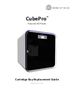
7.
Attach
the
cable
connector
to
the
desired
printer
interface
connector
as
shown
in
“Interface
Connections
(Cabinet
and
Pedestal)”
on
page
22.
8.
Secure
the
cable
to
the
printer
using
the
upper
and
lower
cable
standoffs.
9.
Guide
the
power
cable
up
through
the
hole
in
the
lower
right
back
corner
of
the
cabinet
(see
Figure
15
on
page
18).
10.
Thread
the
power
cord
inside
the
bracket
where
the
gas
spring
is
attached.
11.
Plug
the
power
cord
into
the
printer
AC
power
connector,
then
into
the
AC
power
outlet.
IMPORTANT:
Printer
power
should
be
supplied
from
a
separate
AC
circuit
protected
at
10
amperes
for
100-120
volts
or
5
amperes
for
200-240
volts
at
50
or
60
Hertz.
12.
Turn
the
printer
on.
13.
Continue
with
“Install
the
Ribbon
and
Paper”
on
page
24.
I/O Plate
I/O Connector
Cable
Connector
c2qu0031
Figure
19.
Upper
Inside
View
of
the
Cabinet
Model
Showing
Cable
Connector
Attachment
Connect
the
Interface
and
Power
Cables
Basic
Operating
Procedures
21
|
|
|
|
|
|
|
|
|
Summary of Contents for InfoPrint 6500
Page 2: ......
Page 8: ...vi Infoprint 6500 Quick Start Guide ...
Page 68: ...Quick Setup Menu 58 Infoprint 6500 Quick Start Guide ...
Page 79: ...Korea JEITA Statement Notices 69 ...
Page 82: ...72 Infoprint 6500 Quick Start Guide ...
Page 84: ...74 Infoprint 6500 Quick Start Guide ...
Page 87: ......
Page 88: ... Printed in USA S544 5968 01 ...