background image

Welcome. . .

This

contains information for

setting up, configuring, and
using your BladeCenter T unit.

For detailed information about
your BladeCenter T unit, view
the publications on the

You can also find the most
current information about your
BladeCenter T unit and servers
on the IBM Web site at:
http://www.ibm.com/pc/support

Installation

Guide

and User’s

Documentation CD.

Installation and
User’s Guide

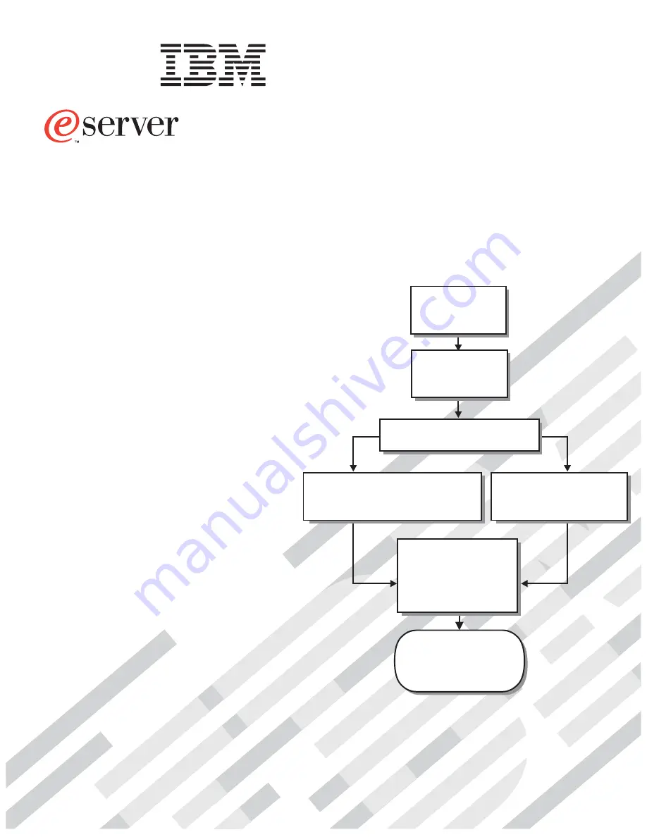
Install and

start the blade

servers

Using ServerGuide

Go to the Web for instructions,

http://www.ibm.com/pc/support

Using the NOS

installation instructions

at www.ibm.com/pc/support

Install additional

applications, such as

IBM systems management

software and IBM

ServeRAID programs on

the blade servers

System is ready to use.

Go to the Server Support

flowchart to register

and profile your server.

Install the

BladeCenter T unit

in the rack.

BladeCenter T

Types 8720 and 8730

Install an operating system on each
blade server (choose one method)

Summary of Contents for BladeCenter T Type 8720

Page 1: ...Installation and User s Guide Install and start the blade servers Using ServerGuide Go to the Web for instructions http www ibm com pc support Using the NOS installation instructions at www ibm com pc...

Page 2: ...r loose connections and verify that all optional devices you installed are on the ServerProven list You can view the ServerProven list at http www ibm com pc compat Server working properly Problem sol...

Page 3: ...BladeCenter T Types 8720 and 8730 Installation and User s Guide ERserver...

Page 4: ...ment of Limited Warranty Z125 4753 07 11 2002 on page 85 and Appendix C Notices on page 101 First Edition May 2004 Copyright International Business Machines Corporation 2004 All rights reserved US Gov...

Page 5: ...eCenter T type 8720 to dc power 20 Connecting the BladeCenter T type 8730 to ac power 21 Starting the BladeCenter T unit 22 Shutting down the BladeCenter T unit 24 Chapter 3 Removing and installing Bl...

Page 6: ...he management and configuration program 64 Starting the management and configuration program 65 Setting management and configuration program options 67 Configuring the external Ethernet port 67 Config...

Page 7: ...Appendix C Notices 101 Edition notice 101 Trademarks 102 Important notes 102 Product recycling and disposal 103 Battery return program 103 Electronic emission notices 104 Federal Communications Commi...

Page 8: ...vi BladeCenter T Types 8720 and 8730 Installation and User s Guide...

Page 9: ...lleert eerst de veiligheidsvoorschriften Ennen kuin asennat t m n tuotteen lue turvaohjeet kohdasta Safety Information Avant d installer ce produit lisez les consignes de s curit Vor der Installation...

Page 10: ...signal cables v Never turn on any equipment when there is evidence of fire water or structural damage v Disconnect the attached power cords telecommunications systems networks and modems before you o...

Page 11: ...products such as CD ROMs DVD drives fiber optic devices or transmitters are installed note the following v Do not remove the covers Removing the covers of the laser product could result in exposure to...

Page 12: ...device and the power switch on the power supply do not turn off the electrical current supplied to the device The device also might have more than one power cord To remove all electrical current from...

Page 13: ...ect a problem with one of these parts contact a service technician Statement 12 CAUTION The following label indicates a hot surface nearby Statement 13 DANGER Overloading a branch circuit is potential...

Page 14: ...t remove all the blades to reduce the weight Statement 21 CAUTION Hazardous energy is present when the blade is connected to the power source Always replace the blade cover before installing the blade...

Page 15: ...connectors for USB keyboard video mouse and network interfaces Performance ease of use reliability robustness NEBS ETSI compliance and expansion capabilities were key considerations in the design of t...

Page 16: ...deCenter T unit v Top of the BladeCenter T unit v Front of the bezel assembly v Front of the BladeCenter T unit The labels on the top and the front of the bezel assembly of the BladeCenter T unit are...

Page 17: ...t contains translated caution and danger statements Each caution and danger statement that appears in the documentation has a number that you can use to locate the corresponding statement in your lang...

Page 18: ...BladeCenter T option These documents contain instructions for setting up and configuring the option such as a switch module and a description of the option features Additional documents might be inclu...

Page 19: ...ers Front bezel with changeable filter Upgradeable microcode v Management module firmware v I O module firmware not all I O module types v Blade server service processor firmware BIOS service processo...

Page 20: ...e microcode v Management module firmware v I O module firmware not all I O module types v Blade server service processor firmware BIOS service processor Size 8 U v Height 349 25 mm 13 75 in or 8 U v D...

Page 21: ...the following procedures to start the Documentation Browser v If Autostart is enabled insert the CD into your CD ROM drive The Documentation Browser starts automatically v If Autostart is disabled or...

Page 22: ...tion of a potentially lethal or extremely hazardous procedure step or situation What the BladeCenter T unit offers The design of the BladeCenter T unit takes advantage of advancements in server techno...

Page 23: ...odule fails the secondary redundant management module becomes the active management module containing the current BladeCenter T configuration and status information You can then replace the failed man...

Page 24: ...ard mouse and video ports and the USB port across the multiple blade servers The service processor in each blade server provides blade server system monitoring event recording and alert capability See...

Page 25: ...oring for blower power temperature and voltage v Built in monitoring for module redundancy v Customer support center 24 hours a day 7 days a week1 v Error codes and messages v Fault resistant startup...

Page 26: ...To maintain proper system cooling each module bay must contain either a module or a filler module each blade bay must contain either a blade server or a filler blade Front view The following illustra...

Page 27: ...nents controls and LEDs on page 51 for details about the components and indicators Rear view Type 8730 The following illustration shows the components on the rear of the BladeCenter T Type 8730 unit I...

Page 28: ...14 BladeCenter T Types 8720 and 8730 Installation and User s Guide...

Page 29: ...ng any blowers power modules or blade servers in the BladeCenter T unit v If your BladeCenter unit has blowers power modules or blade servers already installed remove them first See Chapter 3 Removing...

Page 30: ...y of the hot swap modules in the BladeCenter T unit You must shut down the operating system and turn off a hot swap blade server on the front of the BladeCenter T unit before removing the blade server...

Page 31: ...object with a different potential The ESD wrist strap safely channels the electricity from your body to a proper ground the BladeCenter T unit Use an ESD wrist strap whenever you are working on the B...

Page 32: ...ackage touch it to an unpainted metal part of the system unit for at least 2 seconds This drains static electricity from the package and from your body v Remove the device from its package and install...

Page 33: ...properly wired outlets any equipment that will be attached to this product v When possible use one hand only to connect or disconnect signal cables v Never turn on any equipment when there is evidence...

Page 34: ...modules The left connection looking from the rear supplies power to power module bays 2 and 4 and the connection on the right supplies power to power module bays 1 and 3 Each dc terminal has four M6...

Page 35: ...er unit connect one end of a power cord into input power connector 1 and 2 on the rear of the BladeCenter T unit and the other end of each power cord into a 220 volt power distribution unit PDU that i...

Page 36: ...ed instructions AC in LED DC out LED DC in LED Error LED AC power module DC power module DC out LED Error LED Make sure that the LEDs on the power modules indicate that they are operating correctly Ma...

Page 37: ...or turns off the blade server if local power control has not been disabled through the management module 4 The blade server power button turns on the blade server only if the green power light on the...

Page 38: ...power control button on the device and the power switch on the power supply do not turn off the electrical current supplied to the device The device also might have more than one power cord To remove...

Page 39: ...n page 51 for the location of each module These modules supply common functions to the blade servers that are installed in the blade bays at the front of the BladeCenter T unit The KVM module and medi...

Page 40: ...andling static sensitive devices on page 17 This information will help you work safely with your BladeCenter T unit and options 2 If you are installing or removing a module at the front of the BladeCe...

Page 41: ...ed filter and generate system alerts based on the severity of the airflow reduction The typical service interval for the filter is approximately three to six months depending on your environment See t...

Page 42: ...e bezel 2 Lift the bezel assembly up and out of the BladeCenter T unit Carefully set the bezel assembly aside in a safe location Installing the bezel assembly Complete the following steps if you are i...

Page 43: ...peration Power for all four blowers is shared by all installed power modules One failed blower creates a nonredundant configuration If a power module fails or an input power failure occurs BladeCenter...

Page 44: ...ing a functional power module make sure that both the ac power LED and the dc power LED on the remaining power module are lit otherwise shut down the operating systems and turn off all of the blade se...

Page 45: ...wer module from the selected power module bay and set it aside 2 Press the blue release button on the front of the new power module to release the power module handle then move the power module handle...

Page 46: ...See Media tray on page 53 for information about the system status panel controls and indicators System status panel CD ROM drive Media tray USB connectors Use the instructions in this section to remo...

Page 47: ...in the front of the BladeCenter T unit 1 Hold the media tray at the front of each side of the module and orient the media tray to the top of the media tray bay Carefully position the module into the...

Page 48: ...rms USB to PS 2 conversions for the system keyboard and mouse and can send the VGA signal stream to a remote console for viewing See Management module controls and indicators on page 52 for informatio...

Page 49: ...MM Configuration you will be able to restore the saved configuration file to the replacement management module 4 If you have just installed a second management module in the BladeCenter T unit do not...

Page 50: ...nagement module to open the release latch Make sure that the release latch on the management module is in the open position 90 from the closed position 6 Holding the management module at the front wit...

Page 51: ...cool the BladeCenter T unit and blade servers All flour blowers are required for redundant system operation Power for all four blowers is shared by all installed power modules One failed blower create...

Page 52: ...module into the bay Installing a blower module Complete the following steps to install a blower module into the rear of the BladeCenter T unit 1 Press the release lever at the end of the release latch...

Page 53: ...on minor alarm major alarm and critical alarm See KVM keyboard video mouse module indicators and input output connectors on page 56 for information about the controls and indicators KVM module CRT MJR...

Page 54: ...ng steps to install the KVM module at the rear of the BladeCenter T unit 1 Hold the KVM module by both thumbscrews Thumbscrew Thumbscrew CRT MJR MNR System status panel 2 Position the KVM module into...

Page 55: ...nnector See the LAN module indicators and input output connectors on page 58 for more information LAN module 2 Alarms 1 Use the instructions in this section to remove or install the LAN module into th...

Page 56: ...n 1 minute install the new LAN module Installing the LAN module Complete the following steps to install a LAN module into the rear of the BladeCenter T unit 1 Hold the LAN module by both thumbscrews 2...

Page 57: ...the BladeCenter T unit The I O module must be compatible with the network interface on each of the I O expansion options For example if you install a Fibre Channel I O expansion card on a blade serve...

Page 58: ...e Ethernet switch module or pass thru module in I O module bay 1 b Make sure that the ports on the switch module or pass thru module are enabled I O Module Tasks Management Advanced Management in the...

Page 59: ...es slightly out of the bay 2 Slide the I O module out of the I O module bay and set it aside 3 Within 1 minute install another I O module or filler module into the bay Installing an I O module Complet...

Page 60: ...nd 4 on the BladeCenter T unit The I O expansion option is attached directly to the blade server and does not occupy an additional blade bay Note If an I O expansion option is installed on any blade s...

Page 61: ...date options are established according to bay number You might need to reconfigure the blade server Attention To maintain proper system cooling do not operate the BladeCenter T unit for more than 20 m...

Page 62: ...m the bay and store in a safe place 4 Make sure that the release latches on the blade server are in the open position horizontal to the blade server 5 Slide the blade server into the bay until it stop...

Page 63: ...ility program and install the blade server operating system See the documentation that comes with the blade server for instructions Removing a blade server Complete the following steps to remove a bla...

Page 64: ...50 BladeCenter T Types 8720 and 8730 Installation and User s Guide...

Page 65: ...n the front of your BladeCenter T unit Management module bay 1 Power module 3 Power module 1 Power module 4 Power module 2 Front panel Media tray ESD connector Management module bay 2 CMM 1 CMM 2 Blad...

Page 66: ...nit this LED is lit on only one v Error When this amber LED is lit it indicates that an error has been detected somewhere on the management module When this LED is lit the system error LED critical ma...

Page 67: ...electrical power from the BladeCenter T unit you must disconnect all power cords from the rear of the BladeCenter T unit v Location This blue LED is for system identification A system administrator or...

Page 68: ...two USB peripheral devices without an external hub If more devices are required you can connect an external hub to any of the built in connectors Power modules AC in LED DC out LED DC in LED Error LED...

Page 69: ...ation All the cooling requirements are met if one blower fails All blowers contain a backflow device that prevents the system from drawing air into the exhaust port of a failed blower The management m...

Page 70: ...interface or a remote management console Alarm LEDs These LEDs provide alarm notifications for the BladeCenter T unit v CRT Critical alarm amber default or red When continuously lit this LED indicate...

Page 71: ...module contains one PS 2 style mouse connector Use this connector to connect a PS 2 mouse to the BladeCenter T unit 6 4 2 1 3 5 v Video connector The BladeCenter T KVM module contains one standard vid...

Page 72: ...console Ethernet connectors The LAN module provides two Ethernet RJ 45 connectors The BladeCenter T LAN module contains two 10 100 Mb Ethernet connectors that provide the remote connections driven fro...

Page 73: ...pen O The electrical specifications for the alarms connector are as follows Outputs Voltage range 0 V dc to 100 V dc maximum current 0 3 A at 100 V dc Current range 0 A to 1 A maximum voltage 30 V dc...

Page 74: ...60 BladeCenter T Types 8720 and 8730 Installation and User s Guide...

Page 75: ...he management module to configure the port completely and to configure the rest of the BladeCenter T unit v The internal Ethernet port on the management module for communication with the I O modules s...

Page 76: ...login IDs and passwords v Selecting recipients for alert notification of specific events v Monitoring the status of the BladeCenter T unit and blade servers v Controlling the BladeCenter T unit and bl...

Page 77: ...ng a cross over cable or you can make the connection through an Ethernet switch The right Ethernet port on the LAN module is driven by management module 1 and the left Ethernet port of the LAN module...

Page 78: ...Ethernet port connection in one of the following ways v If you have an accessible active and configured dynamic host configuration protocol DHCP server on the network the host name IP address gateway...

Page 79: ...ser name and password If you are logging in to the management module for the first time you can obtain your user name and password from your system administrator All login attempts are documented in t...

Page 80: ...Note The upper left corner of the management and configuration window shows the location and identity of the active management module 66 BladeCenter T Types 8720 and 8730 Installation and User s Guide...

Page 81: ...t connection v If you plan to use redundant management modules and want both to use the same IP address disable DHCP and configure and use a static IP address the IP configuration information will be...

Page 82: ...rvers to the network you must have an Ethernet switch module installed in I O module bay 1 or 2 or a pass thru module in I O module bay 1 or 2 connected to an external Ethernet switch If you have an I...

Page 83: ...r the secondary Ethernet controller takes over network communication using the I O module associated with that controller 2 Install a switch module or a pass thru module that is connected to external...

Page 84: ...2 controller 1 to switch A and controller 2 to switch B in the illustration In this configuration the default the blade servers share access to four external ports on each switch There is no internal...

Page 85: ...rt in the switch module in I O module bay 2 switch B in this illustration in the BladeCenter T units is connected to another external LAN switch Observe the following guidelines when creating this top...

Page 86: ...ced features Notes 1 Some tasks such as software distribution require an in band connection from IBM Director Server through a campus public LAN to a switch module port 2 See the IBM Support Web site...

Page 87: ...can use the management module Web interface to assign a new static IP address for each BladeCenter T unit If DHCP is not used and you do not assign a new static IP address for each BladeCenter T unit...

Page 88: ...74 BladeCenter T Types 8720 and 8730 Installation and User s Guide...

Page 89: ...tartup and generates error messages if problems are found The system diagnostic program Real Time Diagnostics Version 1 3 tests the major components of your BladeCenter T unit It is run from the IBM D...

Page 90: ...sts If you suspect a problem with your monitor see the information that comes with the monitor for instructions for testing and adjusting the monitor If you cannot diagnose the problem call for servic...

Page 91: ...e problem remains call for service All other symptoms Troubleshoot the blade server that is the current owner of the keyboard video and monitor Power problems Device Suggested action The BladeCenter T...

Page 92: ...m status panels on the BladeCenter T unit is lit one or more error LEDs on the BladeCenter T components also might be on These LEDs help identify the cause of the problem Identifying problems using th...

Page 93: ...nfigure the major error LED to be either red or amber through the management module v Check the error log for messages v Look for an error LED on the modules and blade servers to locate the component...

Page 94: ...le the BladeCenter T unit continues to function using the redundant module Blower module System error The blower has failed or is operating too slowly Reseat the blower module If the problem remains r...

Page 95: ...oards such as the 28L3644 37L0888 keyboard you will need to hold down the Shift key while entering this key sequence Notes 1 It can take up to 20 seconds for the operating system in the switched to bl...

Page 96: ...s the current KVM owner is displayed on the monitor Attention Do not switch the CD ROM drive and USB ports to another blade server while a transaction is taking place on the CD ROM drive Activity ligh...

Page 97: ...stance by following the troubleshooting procedures that IBM provides in the online help or in the publications that are provided with your system and software The information that comes with your syst...

Page 98: ...or information about which products are supported by Support Line in your country or region go to http www ibm com services sl products For more information about Support Line and other IBM services g...

Page 99: ...e removal of parts and their return to IBM A part that replaces a removed part will assume the warranty service status of the removed part Unless IBM specifies otherwise these warranties apply only in...

Page 100: ...an IBM Internet Web site or from other electronic media and following the instructions that IBM provides If your problem can be resolved with a Customer Replaceable Unit CRU e g keyboard mouse speaker...

Page 101: ...sit in those cases where IBM is responsible for the transportation charges Neither IBM nor your reseller are responsible for any of your confidential proprietary or personal information contained in a...

Page 102: ...obligations are subject to the courts of the country in which you acquired the Machine Part 2 Country unique Terms AMERICAS ARGENTINA Governing Law The following is added after the first sentence Any...

Page 103: ...goods are of a kind ordinarily acquired for personal domestic or household use or consumption then none of the limitations in this paragraph apply Governing Law The following replaces laws of the cou...

Page 104: ...ed under this heading Disputes arising out of or in connection with this Statement of Limited Warranty shall be finally settled by arbitration which shall be held in Bangalore India in accordance with...

Page 105: ...MAGES MORAL INCIDENTAL OR INDIRECT DAMAGES FOR ANY ECONOMIC CONSEQUENTIAL DAMAGES OR Arbitration The following is added under this heading Disputes arising out of or in connection with this Statement...

Page 106: ...kraine you may obtain warranty service for that Machine in any of those countries from either 1 an IBM reseller approved to perform warranty service or 2 from IBM If you purchase a Machine in a Middle...

Page 107: ...registered office and or commercial site location only are competent 4 in France Algeria Benin Burkina Faso Cameroon Cape Verde Central African Republic Chad Comoros Congo Republic Djibouti Democrati...

Page 108: ...ki will appoint the chairman EUROPEAN UNION EU THE FOLLOWING TERMS APPLY TO ALL EU COUNTRIES Consumers have legal rights under applicable national legislation governing the sale of consumer goods Such...

Page 109: ...nternal Code LIC The above limitation shall not apply to damages for bodily injuries including death and damages to real property and tangible personal property for which IBM is legally liable 2 UNDER...

Page 110: ...ernal Code LIC Applicability of suppliers and resellers unchanged FRANCE Limitation of Liability The following replaces the second sentence of the first paragraph of this section In such instances reg...

Page 111: ...tion Except as expressly provided in these terms and conditions all statutory conditions including all warranties implied but without prejudice to the generality of the foregoing all warranties implie...

Page 112: ...from IBM UNITED KINGDOM Limitation of Liability The following replaces the terms of this section in its entirety For the purposes of this section a Default means any act statement omission or negligen...

Page 113: ...of Warranty Service Worldwide 3 years 2 See Types of Warranty Service for the legend and explanations of warranty service types A warranty period of 3 years on parts and 1 year on labor means that IB...

Page 114: ...ies otherwise the failing Machine suitably packaged to a location IBM designates After IBM has repaired or exchanged the Machine IBM will make it available for your collection or for Mail in Service I...

Page 115: ...TY OF ANY KIND EITHER EXPRESS OR IMPLIED INCLUDING BUT NOT LIMITED TO THE IMPLIED WARRANTIES OF NON INFRINGEMENT MERCHANTABILITY OR FITNESS FOR A PARTICULAR PURPOSE Some states do not allow disclaimer...

Page 116: ...ountries or both UNIX is a registered trademark of The Open Group in the United States and other countries Java and all Java based trademarks and logos are trademarks or registered trademarks of Sun M...

Page 117: ...recycling and disposal This unit contains materials such as circuit boards cables electromagnetic compatibility gaskets and connectors which may contain lead and copper beryllium alloys that require...

Page 118: ...authorized changes or modifications to this equipment Unauthorized changes or modifications could void the user s authority to operate the equipment This device complies with Part 15 of the FCC Rules...

Page 119: ...s been tested and found to comply with the limits for Class A Information Technology Equipment according to CISPR 22 European Standard EN 55022 The limits for Class A equipment were derived for commer...

Page 120: ...ber Used in these countries and regions 02K0546 China 13F9940 Australia Fiji Kiribati Nauru New Zealand Papua New Guinea 13F9979 Afghanistan Albania Algeria Andorra Angola Armenia Austria Azerbaijan B...

Page 121: ...Barbados Belize Bermuda Bolivia Brazil Caicos Islands Canada Cayman Islands Costa Rica Colombia Cuba Dominican Republic Ecuador El Salvador Guam Guatemala Haiti Honduras Jamaica Japan Mexico Micronesi...

Page 122: ...108 BladeCenter T Types 8720 and 8730 Installation and User s Guide...

Page 123: ...Setup Utility program 64 configuring BladeCenter T unit 61 Ethernet controllers 69 connector Ethernet 58 connector continued Ethernet remote management and console 58 input output 58 keyboard 57 KVM...

Page 124: ...ls model number 2 serial number 2 user 2 48 LAN module 41 function 58 LAN module continued installing 42 LEDs Ethernet activity 58 Ethernet link 58 removing 42 LEDs ac power 54 alarm 53 56 critical 53...

Page 125: ...so features reliability availability and serviceability 11 redundant components 9 network connection capabilities 9 reliability features 11 remote connection 63 remote management connector 58 removing...

Page 126: ...States electronic emission Class A notice 104 United States FCC Class A notice 104 USB connectors 54 utility Configuration Setup 64 V video connector 57 video output unexpected or blank 81 W Web brow...

Page 127: ......

Page 128: ...Part Number 88P9320 Printed in USA 1P P N 88P9320...

Reviews: