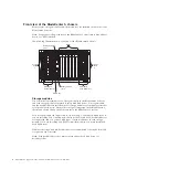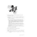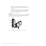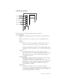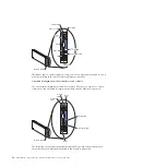
can be turned off through the Web interface of the advanced management
module or through the IBM Director Console.
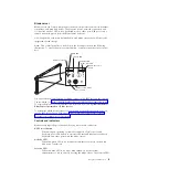
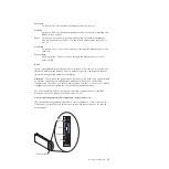
Information LED
When this amber LED is lit, it indicates that information about a system
error for the blade server has been placed in the advanced management
module event log. The information LED can be turned off through the Web
interface of the advanced management module or through the IBM
Director console.
Blade-error LED
When this amber LED is lit, it indicates that a system error has occurred in
the blade server. The blade-error LED will turn off after one of the
following events:
v
Correcting the error
v
Reseating the blade server in the BladeCenter S chassis
v
Cycling the BladeCenter S chassis power
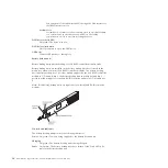
Media-tray select button
Press this button to associate the shared BladeCenter S chassis media tray
(removable-media drive and front-panel USB ports) with the blade server.
The LED on the button flashes while the request is being processed, then is
lit when the ownership of the media tray has been transferred to the blade
server. It can take approximately 20 seconds for the operating system in
the blade server to recognize the media tray.
If there is no response when you press the media-tray select button, use
the advanced management module to determine whether local control has
been disabled on the blade server.
Power-control button
This button is behind the control panel door. Press this button to turn on
or turn off the blade server.
The power-control button has effect only if local power control is enabled
for the blade server. Local power control is enabled and disabled through
the Web interface of the advanced management module.
Press down the power button for five seconds to begin powering down the
blade server.
Power-on LED
This green LED indicates the power status of the blade server in the
following manner:
v
Flashing rapidly: The service processor (BMC) is initializing the blade
server.
v
Flashing slowly: The blade server has completed initialization and is
waiting for a power-on command.
v
Lit continuously: The blade server has power and is turned on.
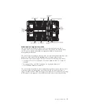
Rear view of the BladeCenter S chassis
Fan modules, I/O modules, power modules, the advanced management module,
and the serial pass-thru module are in the rear of the BladeCenter S chassis.
Note:
Each bay in the BladeCenter S chassis must have either a device or a filler
installed.
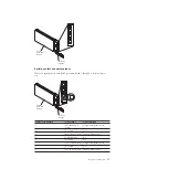
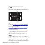
The following illustration shows the rear of the BladeCenter S chassis.
12
BladeCenter S Type 7779/8886: Problem Determination and Service Guide
Summary of Contents for BladeCenter S
Page 1: ...IBM BladeCenter S Type 7779 8886 Problem Determination and Service Guide ...
Page 2: ......
Page 3: ...IBM BladeCenter S Type 7779 8886 Problem Determination and Service Guide ...
Page 128: ...114 BladeCenter S Type 7779 8886 Problem Determination and Service Guide ...
Page 132: ...118 BladeCenter S Type 7779 8886 Problem Determination and Service Guide ...
Page 144: ...130 BladeCenter S Type 7779 8886 Problem Determination and Service Guide ...
Page 145: ......
Page 146: ... Part Number 94Y7083 Printed in USA 1P P N 94Y7083 ...

